


Chapter 2 Function Reference — Config_Alarm_Deadband
NI-DAQ FRM for PC Compatibles 2-64
©
National Instruments Corporation
The channel string has one of the following formats:
xn
SCn!MDn!CHn
AMn!n
where
x: AI for analog input channel.
n: Analog channel, digital port, SCXI chassis, SCXI module number, or
AMUX-64T device number.
SC: Keyword stands for SCXI chassis.
MD: Keyword stands for SCXI module.
CH: Keyword stands for SCXI channel.
AM: Keyword stands for AMUX-64T device.
!: Delimiter.
For example, the following string specifies onboard analog input channel 5 as the trigger
channel:
AI5
The following string specifies SCXI channel 1 in SCXI module 2 of SCXI chassis 4 as the
trigger channel:
SC4!MD2!CH1
The following specifies AMUX channel 34 on the AMUX-64T device 1 as the trigger
channel:
AM1!34
You also can specify more than one channel as the trigger channel by listing all the channels
when specifying the channel number. For example, the following string specifies onboard
analog input channel 2, 4, 6, and 8 as the trigger channels:
AI2,AI4,AI6,AI8
Also, if your channel numbers are consecutive, you can use the following shortcut to specify
onboard analog input channels 2 through 8 as trigger channels:
AI2:8
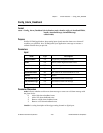
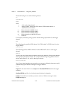
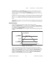
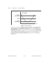
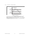
trigLevel is the alarm limit in volts. trigLevel and deadbandWidth determine the trigger
condition.
deadbandWidth specifies, in volts, the hysteresis window for triggering.
handle is the handle to the window you want to receive a Windows message in when
DAQEvent happens.