


Chapter 2 Function Reference — GPCTR_Set_Application
©
National Instruments Corporation 2-229 NI-DAQ FRM for PC Compatibles
between 20 ns and 11.37 hours for 6602 and 455X devices. The timing resolution will be
lower than if you are using the
ND_INTERNAL_20_MHZ timebase.
You can use the
GPCTR_Change_Parameter function after calling
GPCTR_Set_Application and before calling GPCTR_Control with
action =
ND_PROGRAM or ND_PREPARE.
To provide your timebase, you can connect your timebase source to one of the PFI pins on the
I/O connector and change
ND_SOURCE and ND_SOURCE_POLARITY to the appropriate values.
You also can configure the other general-purpose counter for
ND_PULSE_TRAIN_GNR and set
ND_SOURCE of this counter to ND_OTHER_GPCTR_TC to generate pulses with delays and
intervals longer than 160 s for E Series and 445X devices and 11.37 hours for 6602 and 455X
devices.
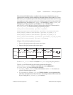
application =
ND_SINGLE_TRIG_PULSE_GNR
In this application, the counter is used for the generation of a single delayed pulse after a
transition on the gate input. By default, this is achieved by using the 20 MHz internal timebase
(
ND_INTERNAL_20_MHZ), so the resolution of timing is 50 ns. By default, the counter counts
down from
ND_COUNT_1 = 5 million to 0 for the delay time, and then down from
ND_COUNT_2 = 10 million to 0 for the pulse generation time to generate a 0.5 s pulse after
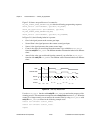
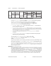
0.25 s of delay. The default gate signal is shown in Table 2-25, and the transition that initiates
the pulse generation is low-to-high. Only the first transition of the gate signal after you arm
the counter initiates pulse generation; all subsequent transitions are ignored.
The default 20 MHz timebase, combined with the counter width (24 bits), lets you generate
pulses with a delay and length between 100 ns and 0.8 s (each), for E Series and 445X devices
only. For 6602 and 455X devices with counter width 32 bits, you can generate pulses with a
delay and length between 100 ns and 214 s long.
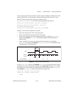
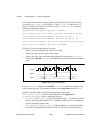
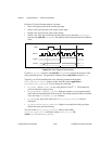
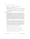
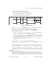
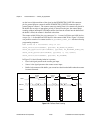
For example, assume that you want to generate a pulse 200 ns long after 150 ns of delay from
the transition of the gate signal. You need to set
ND_COUNT_1 to 150 ns/50 ns = 3 and
ND_COUNT_2 to 200 ns/50 ns = 4. Figure 2-20 shows the scenario of a counter used for
ND_SINGLE_TRIG_PULSE_GNR after the following programming sequence:
GPCTR_Control(deviceNumber, gpctrNum, ND_RESET)
GPCTR_Set_Application(deviceNumber, gpctrNum,
ND_SINGLE_TRIG_PULSE_GNR)
GPCTR_Change_Parameter(deviceNumber, gpctrNum, ND_COUNT_1, 3)
GPCTR_Change_Parameter(deviceNumber, gpctrNum, ND_COUNT_2, 4)
Select_Signal(deviceNumber, gpctrNumOut, gpctrNumOut, ND_LOW_TO_HIGH)
GPCTR_Control(deviceNumber, gpctrNum, ND_PROGRAM)