


Chapter 2 Function Reference — GPCTR_Set_Application
©
National Instruments Corporation 2-241 NI-DAQ FRM for PC Compatibles
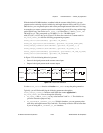
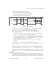
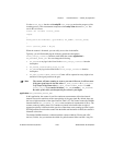
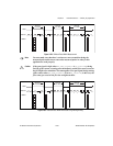
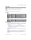
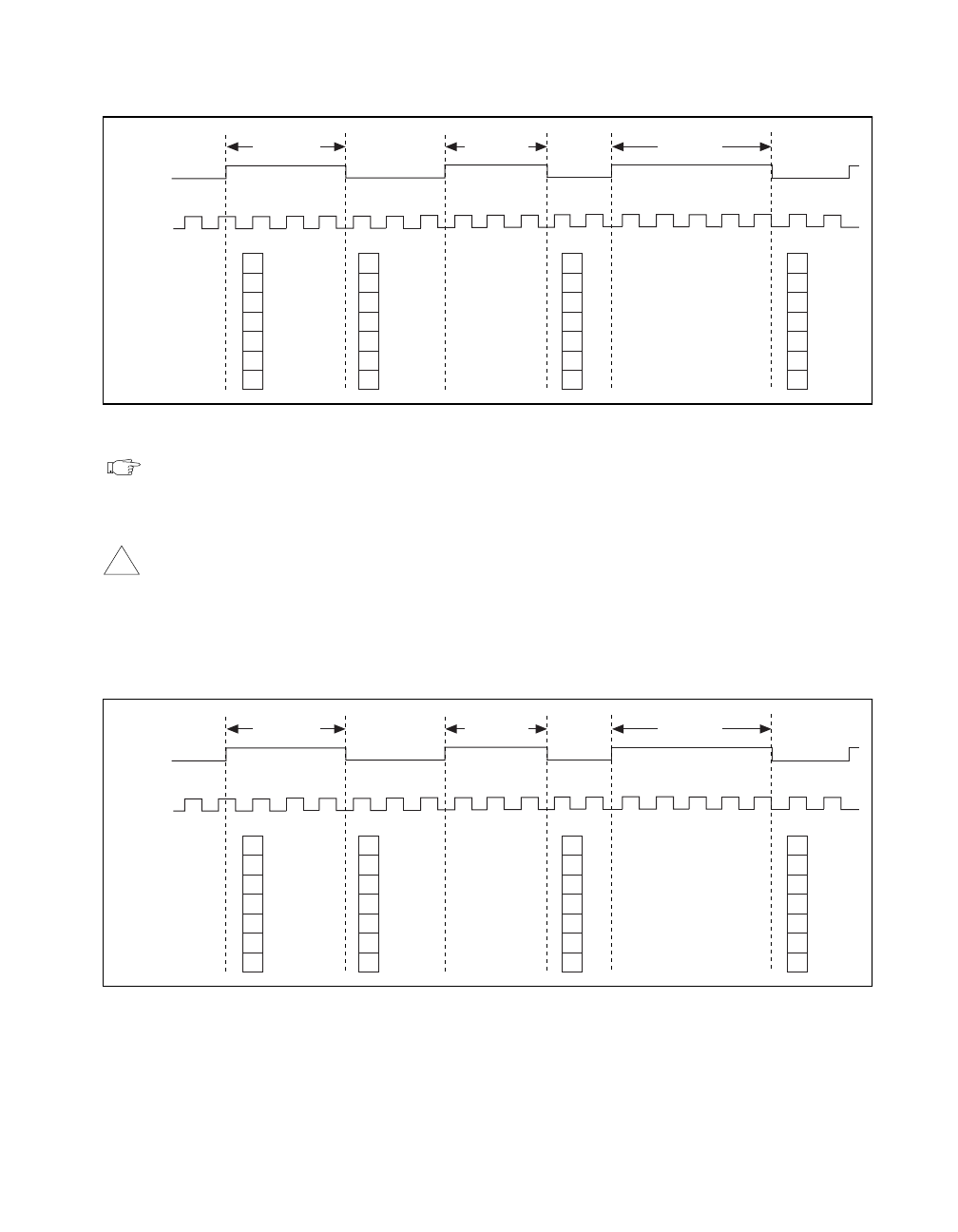
Figure 2-29.
Buffered Pulse Width Measurement
Note
You must make sure that there is at least one source transition during the
measured pulse and between consecutive measured pulses in order for this
application to work properly.
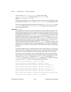
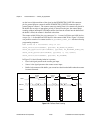
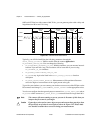
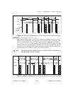
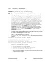
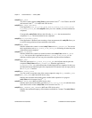
Caution If the gate signal is high (when ND_GATE_POLARITY is ND_POSITIVE) during
arriving of the counter, counting starts immediately, and the first count is saved on
the first high-to-low transition. The same applies to low gate signal during arming
of the counter when
ND_GATE_POLARITY is set to ND_POSITIVE; in this case, the
first count gets saved on the first low-to-high transition.
Figure 2-30.
Buffered Pulse Width when Gate Is High during Arming
Source
Buffer
Gate
Measured
Pulse Width
Measured
Pulse Width
Measured
Pulse Width
123
123
123
4
5
3
3
5
3
3
3
!
Source
Buffer
Gate
Measured
Pulse Width
Measured
Pulse Width
Measured
Pulse Width
123
123
123
4
5
3
3
5
3
3
3