


Chapter 2 Function Reference — GPCTR_Set_Application
NI-DAQ FRM for PC Compatibles 2-230
©
National Instruments Corporation
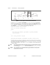
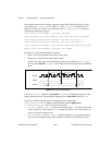
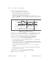
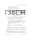
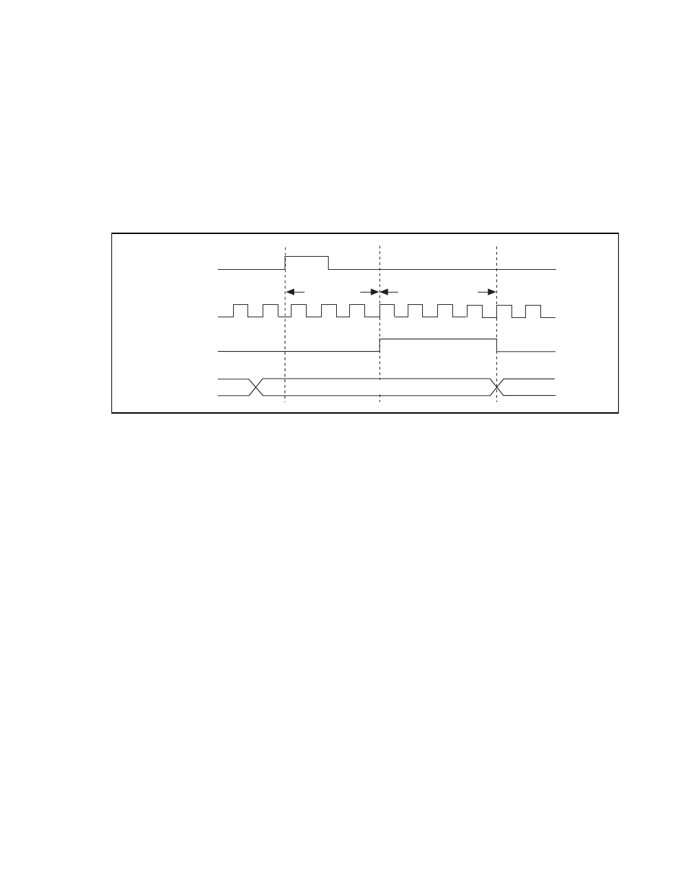
In Figure 2-20, the following behavior is present:
• Gate is the signal present at the counter gate input.
• Source is the signal present at the counter source input.
• Output is the signal present at the counter output.
• Armed is the value you would read from the counter if you called the
GPCTR_Watch
function with entityID =
ND_ARMED. The different values illustrate behavior at different
times.
Figure 2-20.
Single Triggered Pulse Generation
Use the GPCTR_Watch function with entityID = ND_ARMED to monitor the progress of the
pulse generation process. The generation completes when entityValue becomes
ND_NO.
Typically, you will find modification of the following parameters through the
GPCTR_Change_Parameter function useful when the counter application is
ND_SINGLE_TRIG_PULSE_GNR. You can change the following:
•
ND_COUNT_1 and ND_COUNT_2 to any value between 2 and 2
24
– 1. The defaults are
given for illustrative purposes only.
•
ND_SOURCE to ND_INTERNAL_100_KHZ. With this timebase, you can generate pulses
with a delay and length between 20 µs and 160 s. The timing resolution will be lower than
if you are using
ND_INTERNAL_20_MHZ timebase.
•
ND_GATE to any legal value listed in the GPCTR_Change_Parameter function
description.
•
ND_GATE_POLARITY to
ND_NEGATIVE. A high-to-low transition of the gate signal
initiates the pulse generation timing.
You can use the
GPCTR_Change_Parameter function after calling
GPCTR_Set_Application and before calling GPCTR_Control with
action =
ND_PROGRAM or ND_PREPARE.
Source
Armed
No
Output
No
Count_1 = 3
Count_2 = 4
Yes
Gate