


Chapter 2 Function Reference — CTR_FOUT_Config
©
National Instruments Corporation 2-97 NI-DAQ FRM for PC Compatibles
4: Internal 1 kHz clock used as timebase (1 ms resolution).
5: Internal 100 Hz clock used as timebase (10 ms resolution).
6: SOURCE1 used as timebase if FOUT_port = 1 or SOURCE 6 used as timebase
if FOUT_port = 2.
7: SOURCE2 used as timebase if FOUT_port = 1 or SOURCE 7 used as timebase
if FOUT_port = 2.
8: SOURCE3 used as timebase if FOUT_port = 1 or SOURCE 8 used as timebase
if FOUT_port = 2.
9: SOURCE4 used as timebase if FOUT_port = 1 or SOURCE 9 used as timebase
if FOUT_port = 2.
10: SOURCE5 used as timebase if FOUT_port = 1 or SOURCE 10 used as timebase
if FOUT_port = 2.
11: GATE 1 used as timebase if FOUT_port = 1 or GATE6 used as timebase
if FOUT_port = 2.
12: GATE 2 used as timebase if FOUT_port = 1 or GATE7 used as timebase
if FOUT_port = 2.
13: GATE 3 used as timebase if FOUT_port = 1 or GATE8 used as timebase
if FOUT_port = 2.
14: GATE 4 used as timebase if FOUT_port = 1 or GATE9 used as timebase
if FOUT_port = 2.
15: GATE 5 used as timebase if FOUT_port = 1 or GATE10 used as timebase
if FOUT_port = 2.
division is the divide-down factor for generating the clock. The clock frequency is then equal
to (timebase frequency)/division.
Range: 1 through 16.
Using This Function
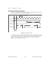
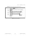
Generates a 50% duty-cycle output clock at the programmable frequency output signal FOUT
if mode = 1; otherwise, the FOUT signal is a low-logic state. The frequency of the FOUT
signal is the frequency corresponding to timebase divided by the division factor.