


Chapter 2 Function Reference — Calibrate_1200
©
National Instruments Corporation 2-51 NI-DAQ FRM for PC Compatibles
obtained during the process remain in use by the DACs until the device is
initialized again.
Note The ADC must be in referenced single-ended and bipolar mode and fully
calibrated (using calOP = 2) for successful calibration of the DACs.
4: Reserved.
5: Edit the default load table so that the set of constants in the area identified by
EEPROMloc (1–6, 9 or 10) become the default calibration constants for the
ADC. NI-DAQ changes either the unipolar or bipolar pointer in the default load
table depending on the polarity those constants are intended for. The factory
default for the ADC unipolar pointer is EEPROMloc = 9. The factory default for
the ADC bipolar pointer is EEPROMloc = 10. You can specify any user area in
EEPROMloc after you have run a calibration on the ADC and saved the
calibration constants to that user area. Or, you can specify EEPROMloc = 9 or
10 to reset the default load table to the factory calibration for unipolar and bipolar
mode respectively.
6: Edit the default load table so that the set of constants in the area identified by
EEPROMloc (1–6, 9 or 10) become the default calibration constants for the
DACs. NI-DAQ’s behavior for calOP = 6 is identical to that for calOP = 5. Just
substitute DAC everywhere you see ADC.
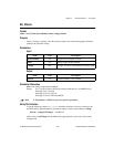
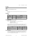
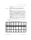
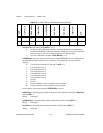
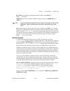
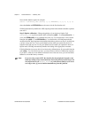
The following table summarizes the possible values of other parameters depending on the
value of calOP.
Table 2-16.
Possible Calibrate_1200 Parameter Values
calOP
saveNewCal
EEPROMloc
calRefChan
grndRefChan
DAC0chan
DAC1chan
calRefVolts
gain
1 ignored 0–10 ignored ignored ignored ignored ignored ignored
2 0 or 1 1–6 AI chan
connected
to voltage
source
(0–7)
AI chan
connected
to ground
(0–7)
ignored ignored the voltage
of the
voltage
source
1, 2, 5, 10,
50, or 100
3 0 or 1 1–6 ignored ignored AI chan
connected to
DAC0Out
(0–7)
AI chan
connected to
DAC1Out
(0–7)
ignored 1, 2, 5, 10,
50, or 100