


Chapter 2 Function Reference — GPCTR_Set_Application
NI-DAQ FRM for PC Compatibles 2-240
©
National Instruments Corporation
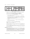
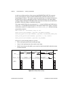
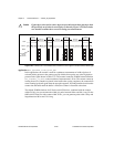
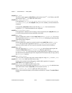
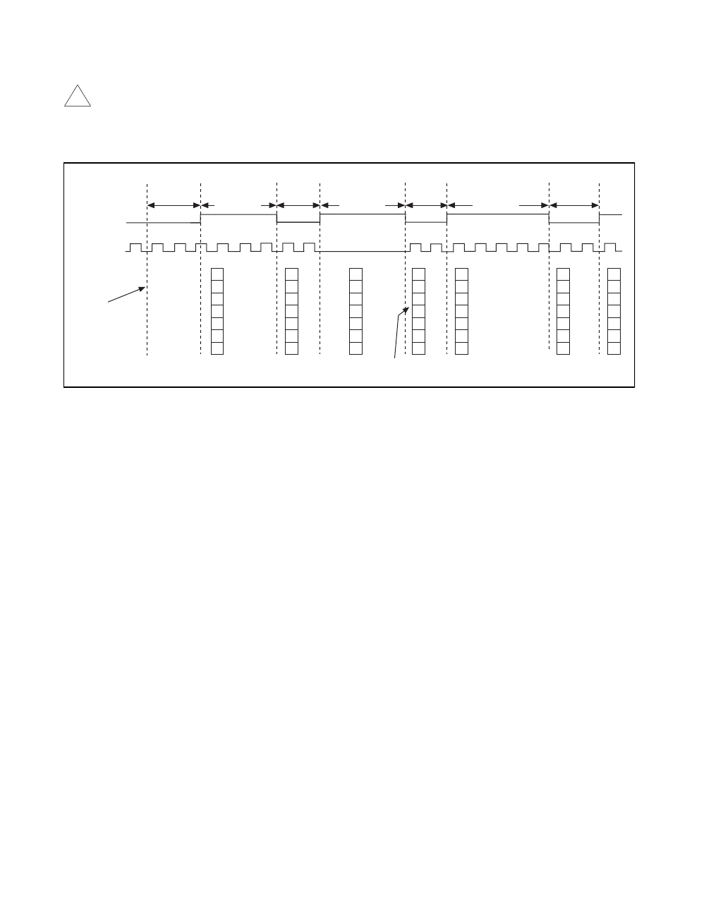
Caution If gate edges arrive and no source edges are present between those gate edges, then
the previously saved value is saved again, as shown by Figure 2-28. Please make
sure that this condition does not occur during your measurement.
Figure 2-28.
Buffered Semi-Period Measurement when No Source Edges Are Present between Gate Edges
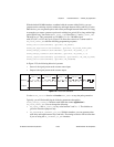
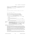
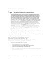
application = ND_BUFFERED_PULSE_WIDTH_MSR
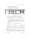
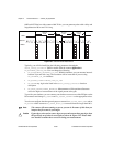
In this application, the counter is used for continuous measurement of width of pulses of
selected polarity present at the counter gate. By default, those pulses are active high pulses
present on the signal shown in Table 2-25. The counter counts the 20 MHz internal timebase
(
ND_INTERNAL_20_MHZ), so the resolution of measurement is 50 ns. The counter counts up
starting from 0; its contents are placed in the buffer after a pulse completes; the counter then
starts counting up from 0 again when the next pulse appears. NI-DAQ transfers data from the
counter into the buffer until the buffer is filled; the counter is disarmed at that time.
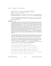
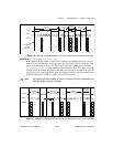
The default 20 MHz timebase for E Series and 445X devices, combined with the counter
width (24 bits), lets you measure the width of a pulse between 100 ns and 0.8 s long. For the
6602 and 455X devices with counter width 32 bits, you can generate pulses with a delay and
length between 100 ns and 214 s long.
!
Source
Buffer
3
Gate
1
312
45
2
12
12
1
2
Measured
Semi-Period
3
Measured
Semi-Period
Measured
Semi-Period
Measured
Semi-Period
3
1
2
Measured
Semi-Period
Measured
Semi-Period
Measured
Semi-Period
3
3
3
3
2
2
3
3
2
2
2
3
3
2
2
5
2
3
3
2
5
2
2
2
3
3
2
The instant
you arm
the counter
Warnin
g