


Chapter 2 Function Reference — WFM_Load
NI-DAQ FRM for PC Compatibles 2-430
©
National Instruments Corporation
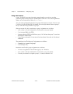
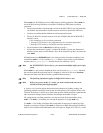
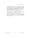
DAQ Hardware Overview Guide. You must use the entire 16,384 points of buffer to define
one cycle of your waveform. For example, to generate different frequencies of a sinusoidal
waveform, you must load only one cycle of a sine wave to fit the entire 16,384 points of the
buffer. To generate different frequencies of the loaded waveform, you must then call
WFM_Load again with mode = 4. Notice that only one buffer is allowed for a mode of 2.
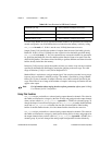
Use mode = 3 for loading waveforms which are arbitrary in nature and for which very deep
memory is required. Very complex waveforms also can be generated using the linking and
looping capabilities of the device in this mode. This mode is referred to as arbitrary waveform
generation (ARB) mode. For more details on the ARB mode, refer to Chapter 16, DAQArb
5411 Devices, in the DAQ Hardware Overview Guide. The minimum size of the buffer is
256 samples, and the total number of samples must be a multiple of 8 samples. You can call
WFM_Load a multiple number of times, consecutively, to load different buffers. When you
do this, you must assign each buffer an ID using the iterations parameter. The first buffer
should have an ID of 0 and the successive buffers always should have the buffer ID of one
more than the previously loaded buffer. To generate a sequence of these buffers in the order
you want, call
WFM_Load again with mode = 4. Notice that a multiple number of buffers are
allowed for mode of 3.
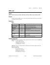
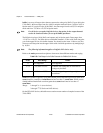
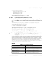
Use mode = 4 for loading a sequence list of buffers (for ARB mode) or frequencies (DDS
mode) to be generated. Each stage in the sequence list is an array of 16-bit values. The total
number of these 16-bit values for a stage depends on the previous mode
WFM_Load mode
being 2 or 3. The structure of this array for one stage in the DDS and ARB mode is as follows.
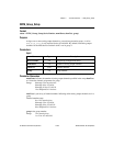
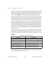
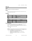
DDS Mode
For each stage, DDS Frequency Word specifies the frequency to be generated of the waveform
loaded into the DDS lookup memory. DDS Frequency Word is 64 bits long and is divided into
four 16-bit unsigned words as shown in the array.
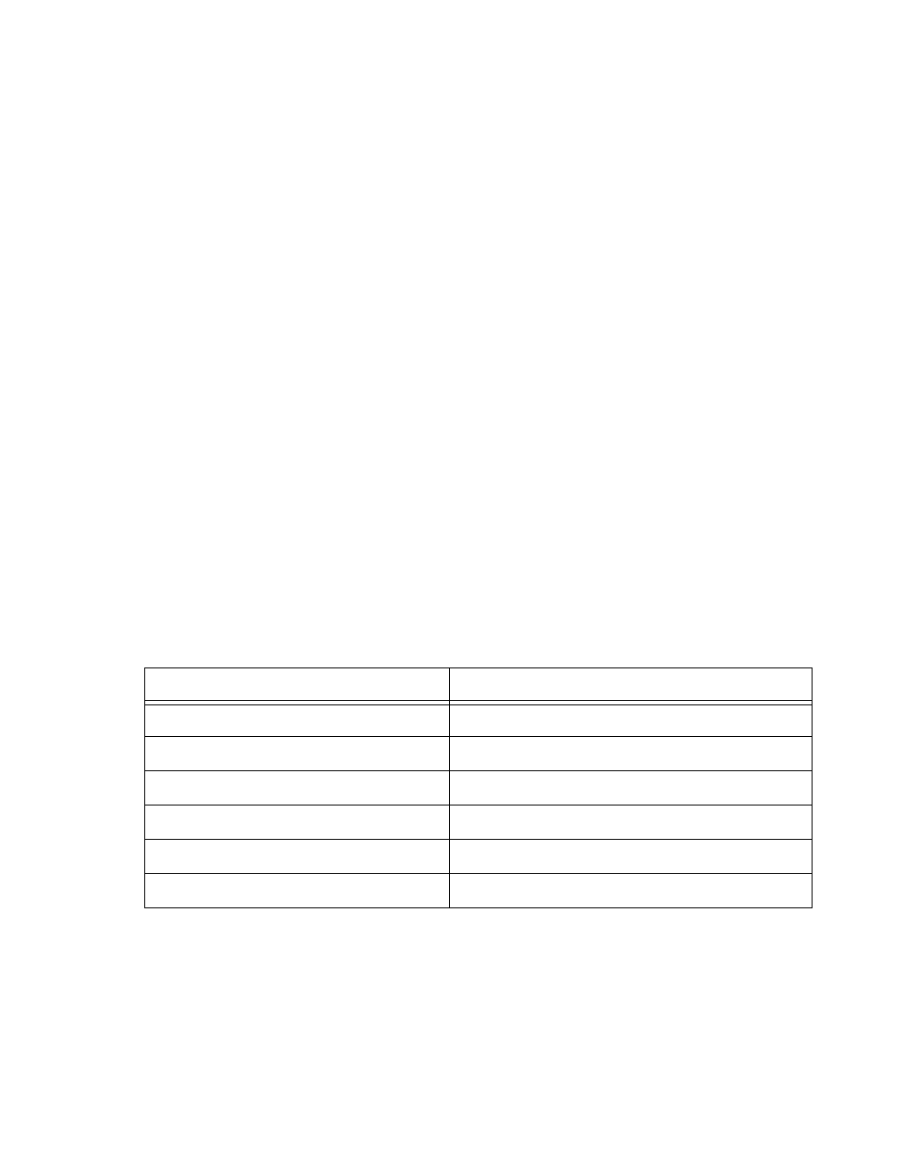
Table 2-42.
Array Structures for DDS Mode
Frequency Array Element
DDS Frequency Word [63:48] ← Array element 0 (range 0 to 65,535)
DDS Frequency Word [47:32] ← Array element 1 (range 0 to 65,535)
DDS Frequency Word [31:16]
← Array element 2 (range 0 to 65,535)
DDS Frequency Word [15:0] ← Array element 3 (range 0 to 65,535)
Duration in 5 MHz Intervals [31:16]
← Array element 4 (range 0 to 65,535)
Duration in 5 MHz Intervals [15:0]
← Array element 5 (range 0 to 65,535)