


Chapter 2 Function Reference — Configure_HW_Analog_Trigger
NI-DAQ FRM for PC Compatibles 2-88
©
National Instruments Corporation
For example, if you set source to ND_THE_AI_CHANNEL, the channel you are interested in is
in bipolar mode, you want a gain of 100, and you want to set the voltage window for triggering
to +35 mV and +45 mV for your original signal (that is, signal before amplification by the
onboard amplifier), you should make the following programming sequence:
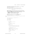
12-bit boards:
status = Configure_HW_Analog_Trigger (deviceNumber,
ND_ON, 218, 243, mode,
ND_THE_AI_CHANNEL)
Status = Select_Signal (deviceNumber,
ND_IN_START_TRIGGER, ND_PFI_0,
ND_LOW_TO_HIGH)
16-bit boards:
status = Configure_HW_Analog_Trigger (deviceNumber,
ND_ON, 2764, 2969, mode,
ND_THE_AI_CHANNEL)
status = Select_Signal (deviceNumber,
ND_IN_START_TRIGGER, ND_PFI_0,
ND_LOW_TO_HIGH)
To calculate lowValue in the previous example, do the following:
1. Multiply 35 mV by 100 to adjust for the gain to get 3.5 V.
2. Use the following formula to map the 3.5 V from the –5 V to +5 V scale to a value on the
0 to 255 (0–4,095 for the 16-bit boards) scale:
value = (3.5/5 + 1) * 128 = 218 (for the 0 to 255 case)
Use the following formula to map the 3.5 V from the -10 V to +10 V scale to a value on
the 0 to 4,095 scale:
value = (3.5/10 +1) * 2,048 = 2,764 (for the 0 to 4,095 case)
In general, the scaling formulas are as follows:
• For an analog input channel in the bipolar mode:
12-bit boards: value = (voltage/5 + 1) *128
16-bit boards: value = (voltage/10 + 1) *2048
• For an analog input channel in the unipolar mode:
12-bit boards: value = (voltage/10) *256
16-bit boards: value = (voltage/10) *4096
• For the PFI0/TRIG1 pin:
12-bit boards: value = (voltage/10 + 1)*128
16-bit boards: value = (voltage/10 + 1) * 2048