


Chapter 2 Function Reference — Config_Alarm_Deadband
©
National Instruments Corporation 2-65 NI-DAQ FRM for PC Compatibles
alarmOnMessage and alarmOffMessage are messages you define. When the alarm-on
condition occurs, NI-DAQ passes alarmOnMessage back to you. Similarly, when the
alarm-off condition occurs, NI-DAQ passes alarmOffMessage back to you. The messages
can be any value.
In Windows, you can set the message to a value including any Windows predefined messages
such as
WM_PAINT. However, to define your own message, you can use any value ranging
from
WM_USER (0x400) to 0x7fff. This range is reserved by Microsoft for messages you
define.
callbackAddr is the address of the user callback function. NI-DAQ calls this function when
DAQEvent occurs. See
Config_DAQ_Event_Message for restrictions on this parameter.
Using This Function
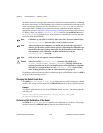
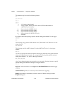
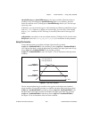
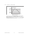
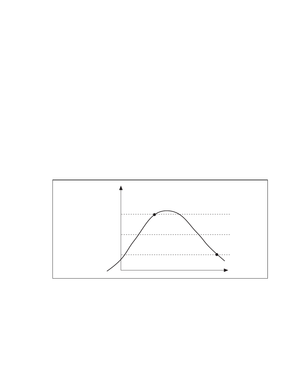
To meet the high alarm-on condition, the input signal must first go below
(trigLevel - deadbandWidth/2) volts and then go above (trigLevel + deadbandWidth/2)
volts. On the other hand, to meet the high alarm-off condition, the input signal must first go
above (trigLevel + deadbandWidth/2) volts and then go below
(trigLevel – deadbandWidth/2) volts. See Figure 2-1 for an illustration of the high alarm
condition.
Figure 2-1.
High Alarm Deadband
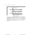
The low alarm deadband trigger condition is the opposite of the high alarm deadband
trigger condition. To meet the low alarm-on condition, the input signal must first go above
(trigLevel + deadbandWidth/2) and then go below (trigLevel - deadbandWidth/2). On
the other hand, to meet the low alarm-off condition, the input signal must first go below
(trigLevel – deadbandWidth/2) and then go above (trigLevel + deadbandWidth/2).
See Figure 2-2 for an illustration of the low alarm condition.
on
off
trigLevel +
deadbandWidth/2
trigLevel -
deadbandWidth/2
trigLevel
On: high alarm on
Off: high alarm off
Time