


Chapter 2 Function Reference — GPCTR_Change_Parameter
NI-DAQ FRM for PC Compatibles 2-202
©
National Instruments Corporation
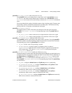
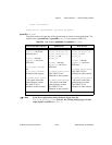
Synchronization on default Source and Up/Down pins is enabled when you call
GPCTR_Change_Parameter with paramID = ND_INPUT_CONDITIONING and
paramValue as any of the quadrature modes or the two-pulse counting mode.
You can enable Z-Index pulse for quadrature encoders by making a
GPCTR_Change_Parameter
call with paramID = ND_INDEX_PULSE and
paramValue =
ND_YES. The Z-Index signal should be connected to default gate for the
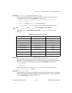
counter that is being used. The value to which the count should reset in the event of a Z-Index
pulse can be specified by making a
GPCTR_Change_Parameter call with paramID =
ND_COUNT_1
.
Note By default, the counter will start counting from 0. You can alter this by calling
GPCTR_Change_Parameter with a paramID set to ND_INITIAL_COUNT. A good
technique for setting the initial value would be to set it in an invalid range. When
the counter receives a Z-Index, the value of the counter will be placed in a valid
range. This technique will allow you to detect the initial Z-Index.
An example use of this paramID is shown below:
Create u32 variable gpctrNum;
Create u32 variable counterValue;
gpctrNum = ND_COUNTER_0
GPCTR_Control (deviceNumber, gpctrNum, ND_RESET)
GPCTR_Control (deviceNumber, gpctrNum, ND_SIMPLE_CNT)
GPCTR_Change_Parameter (deviceNumber, gpctrNum,
ND_INPUT_CONDITIONING,ND_QUADRATURE_ENCODER_X1)
/*specify that the counter reloads to value of 1000 every time a
Z-Index pulse occurs*/
GPCTR_Change_Parameter (deviceNumber, gpctrNum, ND_Z_INDEX_PULSE,
1000)
/*load the counter initially with a bogus value for Z-Index
detection*/
GPCTR_Change_Parameter (deviceNumber, gpctrNum, ND_COUNT_1, –10000)
GPCTR_Control (deviceNumber, gpctrNum, ND_PROGRAM)
Repeat as long as required by your application
{
/*you can check for a valid value for counterValue here*/
GPCTR_Watch (deviceNumber, gpctrNum, ND_COUNT, counterValue)