


Chapter 2 Function Reference — GPCTR_Set_Application
NI-DAQ FRM for PC Compatibles 2-242
©
National Instruments Corporation
application = ND_BUFFERED_TWO_SIGNAL_EDGE_SEPARATION_MSR
Note
This application is applicable only to 6602 and 455X devices.
In this application, the counter is used for continuous measurement of the time interval
between transitions of the gate and the second gate signal. Measurement starts when the
gate signal is asserted and stops when the second gate signal is asserted. By default, the
measurement is performed between low-to-high transitions of the gate and the second
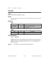
gate signals. The default values for gate and second gate signals for the eight counters
are shown in Table 2-25 and Table 2-26. The counter counts the 20 MHz internal timebase
(
ND_
INTERNAL_20_MHZ
)
, so the resolution of measurement is 50 ns. The counter counts
up starting from 0 when it detects an edge on the gate; its contents are placed in the
buffer after it encounters an edge on the second gate; the counter then starts counting
up from 0 again when another edge occurs on the gate. For single buffer mode (set using
GPCTR_Change_Parameter using paramID = ND_BUFFER_MODE and
paramValue =
ND_SINGLE
)
. NI-DAQ transfers data from the counter into the buffer
until the buffer is filled. Data is continuously placed in the buffer in double-buffer mode
(set using
GPCTR_Change_Parameter using paramID = ND_BUFFER_MODE and
paramValue =
ND_DOUBLE).
The default 20 MHz timebases, combined with the counter width (32 bits), lets you measure
the duration of a pulse between 100 ns and 214 s long.
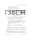
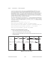
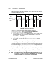
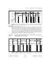
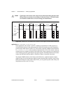
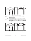
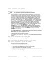
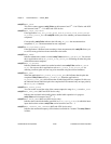
Figure 2-31 shows one possible use of a counter for
ND_BUFFERED_TWO_SIGNAL_EDGE_SEPARATION_MSR
after the following programming
sequence:
GPCTR_Control (deviceNumber, gpctrNum, ND_RESET)
GPCTR_Set_Application (deviceNumber, gpctrNum,
ND_BUFFERED_TWO_SIGNAL_EDGE_SEPARATION_MSR)
GPCTR_Config_Buffer (deviceNumber, gpctrNum, 0, 100, buffer)
GPCTR_Control (deviceNumber, gpctrNum, ND_PROGRAM)
In Figure 2-31, the following behavior is present:
• Gate is the signal present at the counter gate input.
• Second Gate is the signal present at the counter second gate input.
• Source is the signal present at the counter source input.
• Buffer is the contents of the buffer; you can retrieve data from the buffer when the counter
is disarmed or while it is running.