


Chapter 2 Function Reference — DIG_SCAN_Setup
©
National Instruments Corporation 2-189 NI-DAQ FRM for PC Compatibles
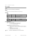
dir selects the direction, input or output, to which the group is to be configured.
0: Port is configured as an input port (default).
1: Port is configured as an output port.
2: Port is configured as a bidirectional port.
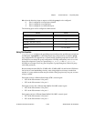
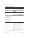
The following ports can be configured as bidirectional:
Using This Function
DIG_SCAN_Setup configures the specified group according to the specified port assignment
and direction. If groupSize is 0, NI-DAQ releases any ports previously assigned to group.
Any configurations not supported by or invalid for the specified group return an error, and
NI-DAQ does not change the group configuration. NI-DAQ subsequently writes to or reads
from ports assigned to a group as a group using
DIG_Block_In and DIG_Block_Out.
NI-DAQ can no longer access any ports assigned to a group through any of the non-group
calls listed previously.
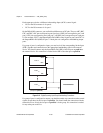
Because each port on the DIO-24, AT-MIO-16D, AT-MIO-16DE-10, and Lab and 1200 Series
devices has its own handshaking circuitry, extra wiring might be necessary to make data
transfer of a group with more than one port reliable. If the group has only one port, no extra
wiring is needed.
Each input port has a different Strobe Input (STB*) control signal.
• PC4 on the I/O connector is for port 0.
• PC2 on the I/O connector is for port 1.
Each input port also has a different Input Buffer Full (IBF) control signal.
• PC5 on the I/O connector is for port 0.
• PC1 on the I/O connector is for port 1.
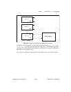
Each output port has a different Output Buffer Full (OBF*) control signal.
• PC7 on the I/O connector is for port 0.
• PC1 on the I/O connector is for port 1.
Device Ports
AT-MIO-16D 2
AT-MIO-16DE-10 2
Lab and 1200 Series devices 0
DIO-24 0
DIO-96 0, 3, 6, and 9