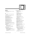
Index
©
National Instruments Corporation I-13 NI-DAQ FRM for PC Compatibles
square wave generation timing considerations,
2-112
status codes, 1-1 to 1-2
format, 1-1
status values (table), 1-1
summary of codes, A-1 to A-23
stepped trigger mode, for DAQArb 5411
devices, 2-34
SYNC duty cycle, 2-35 to 2-36
T
technical support, D-1 to D-2
telephone and fax support, D-2
Timeout_Config function, 2-400 to 2-401
timing diagrams, Mode 0 through Mode 5,
2-252 to 2-253
timing signal name equivalencies, E series
(table), 2-387
trigger functions
Config_ATrig_Event_Message,
2-67 to 2-70
Configure_HW_Analog_Trigger,
2-83 to 2-89
DAQ_StopTrigger_Config,
2-140 to 2-141
trigger generation
ND_ABOVE_HIGH_LEVEL signal
(figure), 2-85
ND_BELOW_LOW_LEVEL signal
(figure), 2-85
ND_HIGH_HYSTERESIS signal
(figure), 2-86
ND_INSIDE_REGION signal (figure),
2-85
ND_LOW_HYSTERESIS signal
(figure), 2-86
trigger modes, for DAQArb 5411 devices,
2-34 to 2-35
triggered pulse generation application,
2-229 to 2-231
triggered pulse width measurement
applications, 2-223 to 2-225
V
variable data types, 1-2 to 1-4
arrays, 1-3
multiple types, 1-3 to 1-4
primary type names (table), 1-3 to 1-4
Visual Basic for Windows, 1-4 to 1-5
voltage calculation, B-5 to B-6
voltage or current output parameters,
2-28 to 2-29
VXIbus trigger mapping (table),
2-387 to 2-388
W
waveform generation functions
definition, 1-13
LabWindows function panel tree, 1-9
NI-DAQ function support (table)
DAQArb, AO-2DC, AT-AO-6/10,
and VXI-AO-48XDC devices,
C-11 to C-12
DSA devices, C-10
Lab/516/DAQCard-500/700 devices,
C-8
MIO and AI devices, C-5
WFM_Chan_Control function, 2-402 to 2-403
WFM_Check function, 2-404 to 2-405
WFM_ClockRate function, 2-406 to 2-410
WFM_DB_Config function, 2-411 to 2-412
WFM_DB_HalfReady function,
2-413 to 2-414
WFM_DB_Transfer function, 2-415 to 2-416
WFM_from_Disk, 2-417 to 2-419
WFM_Group_Control function,
2-420 to 2-422
WFM_Group_Setup function, 2-423 to 2-424
WFM_Load function, 2-425 to 2-433


