


Chapter 2 Function Reference — GPCTR_Set_Application
NI-DAQ FRM for PC Compatibles 2-234
©
National Instruments Corporation
You can use the GPCTR_Change_Parameter function after calling
GPCTR_Set_Application and before calling GPCTR_Control with
action =
ND_PROGRAM or ND_PREPARE.
To provide your timebase, you can connect your timebase source to one of the PFI pins on the
I/O connector and change
ND_SOURCE and ND_SOURCE_POLARITY to the appropriate values.
You also can configure the other general-purpose counter for
ND_PULSE_TRAIN_GNR, and set
ND_SOURCE of this counter to ND_OTHER_GPCTR_TC to generate pulses with delays and
intervals longer than 160 s.
application =
ND_FSK
In this application, the counter is used for generation of frequency shift keyed signals. The
counter generates a pulse train of one frequency and duty cycle when the gate is low, and a
pulse train with different parameters when the gate is high. By default, you get this by using
the 20 MHz internal timebase (
ND_INTERNAL_20_MHZ), so the resolution of timing is 50 ns.
By default, when the gate is low, the counter repeatedly counts down from
ND_COUNT_1 = 5
million to 0 for the delay time, and then down from
ND_COUNT_2 = 10 million to 0 for the
pulse generation time, to generate a train 0.5 s pulses separated by 0.25 s of delay. Also by
default, when the gate is high, the counter repeatedly counts down from
ND_COUNT_3 = 4
million to 0 for the delay time, and then down from
ND_COUNT_4 = 6 million to 0 for the pulse
generation time, to generate a train 0.3 s pulses separated by 0.2 s of delay. The FSK pulse
generation starts as soon as you arm the counter. You must reset the counter to stop the pulse
generation.
The default 20 MHz timebase, combined with the counter width (24 bits), lets you generate
pulses with a delay and length between 100 ns and 0.8 s. For the 6602 devices with counter
width 32 bits, you can generate pulses with a delay and width of 100 ns and 214 s long.
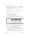
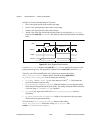
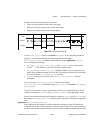
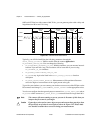
Assume that you want to generate a pulse train with 100 ns low time and 150 ns high time
when the gate is low and with 300 ns low time and 200 ns high time when the gate is high.
You need to set
ND_COUNT_1 to 100 ns/50 ns = 2, ND_COUNT_2 to 150 ns/50 ns = 3,
ND_COUNT_3 to 300 ns/50 ns = 6, and ND_COUNT_4 to 200 ns/50 ns = 4. Figure 2-23 shows
a counter used for
ND_FSK after the following programming sequence:
GPCTR_Control(deviceNumber, gpctrNum, ND_RESET)
GPCTR_Set_Application(deviceNumber, gpctrNum, ND_FSK)
GPCTR_Change_Parameter(deviceNumber, gpctrNum, ND_COUNT_1, 2)
GPCTR_Change_Parameter(deviceNumber, gpctrNum, ND_COUNT_2, 3)
GPCTR_Change_Parameter(deviceNumber, gpctrNum, ND_COUNT_3, 6)
GPCTR_Change_Parameter(deviceNumber, gpctrNum, ND_COUNT_4, 4)
Select_Signal(deviceNumber, gpctrNumOut, gpctrNumOut, ND_LOW_TO_HIGH)
GPCTR_Control(deviceNumber, gpctrNum, ND_PROGRAM)