


Chapter 2 Function Reference — GPCTR_Set_Application
©
National Instruments Corporation 2-235 NI-DAQ FRM for PC Compatibles
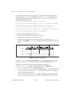
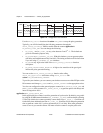
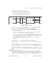
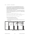
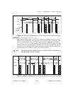
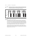
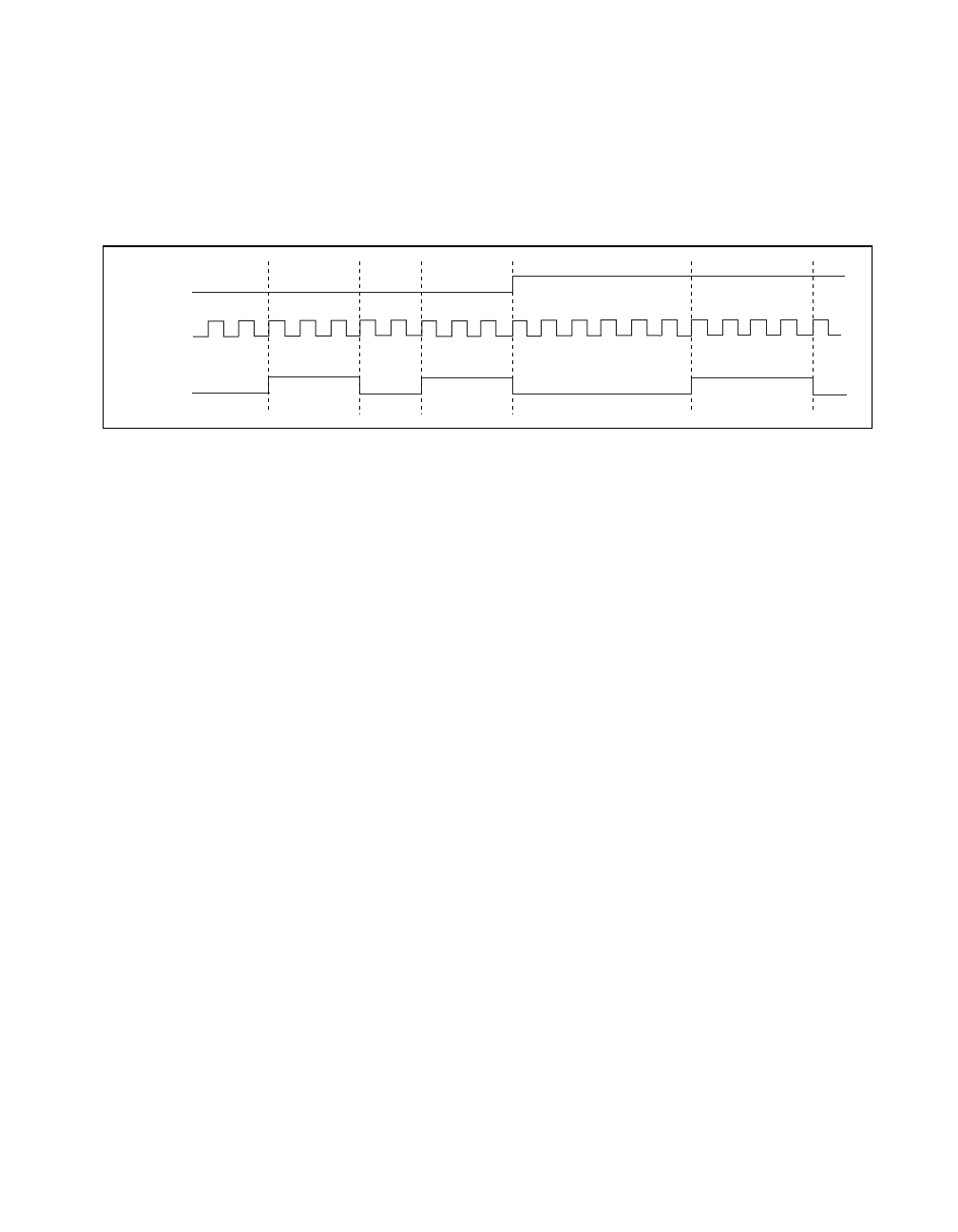
In Figure 2-23, the following behavior is present:
• Gate is the signal present at the counter gate input.
• Source is the signal present at the counter source input.
• Output is the signal present at the counter output.
Figure 2-23.
Frequency Shift Keying
Use the GPCTR_Control function with action = ND_RESET to stop the pulse generation.
Typically, you will find modifying the following parameters through the
GPCTR_Change_Parameter function useful when the counter application is ND_FSK.
You can change the following:
•
ND_COUNT_1, ND_COUNT_2, ND_COUNT_3, and ND_COUNT_4 to any value between
2and 2
24
– 1. The defaults are given for illustrative purposes only.
•
ND_SOURCE to ND_INTERNAL_100_KHZ. With this timebase, you can generate pulses
with a delay and length between 20 µs and 160 s. The timing resolution will be lower than
if you are using the
ND_INTERNAL_20_MHZ timebase.
•
ND_GATE to any legal value listed in the GPCTR_Change_Parameter function
description.
You can use the
GPCTR_Change_Parameter function after calling
GPCTR_Set_Application and before calling GPCTR_Control with action = ND_PROGRAM
or
ND_PREPARE.
To provide your timebase, connect your timebase source to one of the PFI pins on the I/O
connector and change
ND_SOURCE and ND_SOURCE_POLARITY to the appropriate values.
You also can configure the other general-purpose counter for
ND_FSK, and set ND_SOURCE of
this counter to
ND_OTHER_GPCTR_TC to generate pulses with delays and intervals longer than
160 s.
application =
ND_BUFFERED_EVENT_CNT
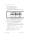
In this application, the counter is used for continuous counting of events. By default, the
counted events are low-to-high transitions on the line given in Table 2-21. Counts present at
specified events of the signal present at the gate are saved in a buffer. By default, those events
Source
Output
2
13 45
6
2121321 3214321
Gate