


Chapter 2 Function Reference — MIO_Calibrate
NI-DAQ FRM for PC Compatibles 2-282
©
National Instruments Corporation
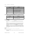
For the AT-MIO-64F-5 and AT-MIO-16X:
1: User calibration area 1.
2: User calibration area 2.
3: User calibration area 3.
4: User calibration area 4.
5: User calibration area 5.
6: User calibration area 6.
7: User calibration area 7.
8: User calibration area 8 (initial load area).
9: Factory calibration area for unipolar (you cannot write to this area).
10: Factory calibration area for bipolar (you cannot write to this area).
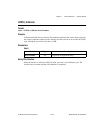
calRefChan is the analog input channel that the calibration voltage is connected to when
calOP is 4.
Range: 0 through 7.
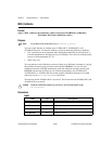
DAC0chan is the analog input channel that DAC0 is connected to when calOP is 3. This
parameter is not applicable to the AT-MIO-64F-5 because its DAC0 is internally wrapped
back.
Range: 0 through 7.
DAC1chan is the analog input channel that DAC1 is connected to when calOP is 3. This
parameter is not applicable to the AT-MIO-64F-5 because its DAC0 is internally wrapped
back.
Range: 0 through 7.
calRefVolts is the value of the DC calibration voltage connected to calRefChan when
calOP is 4.
Range: +6 to +10 V.
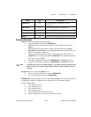
refLoc is the source of the internal voltage reference constants when calOp is 2 or 3. When
calOP is 4, NI-DAQ stores the internal voltage reference constants in refLoc.
1: User reference area 1.
2: User reference area 2.
3: User reference area 3 (AT-MIO-16X and AT-MIO-64F-5 only).
4: User reference area 4 (AT-MIO-16X and AT-MIO-64F-5 only).
6: Factory reference area (you cannot write to this area).
Using This Function
Note
Calibration of your MIO or AI device takes some time. Do not be alarmed if the
MIO_Calibrate function takes several seconds to execute.