


Chapter 2 Function Reference — CTR_Square
©
National Instruments Corporation 2-111 NI-DAQ FRM for PC Compatibles
8: SOURCE3 used as timebase if 1 ≤ ctr v 5 or SOURCE 8 used as timebase
if 6 ≤ ctr ≤ 10.
9: SOURCE4 used as timebase if 1 ≤ ctr ≤ 5 or SOURCE 9 used as timebase
if 6 ≤ ctr ≤ 10.
10: SOURCE5 used as timebase if 1 ≤ ctr ≤ 5 or SOURCE 10 used as timebase
if 6 ≤ ctr ≤ 10.
11: GATE 1 used as timebase if 1 ≤ ctr ≤ 5 or GATE6 used as timebase if
6 ≤ ctr ≤ 10.
12: GATE 2 used as timebase if 1 ≤ ctr ≤ 5 or GATE7 used as timebase if
6 ≤ ctr ≤ 10.
13: GATE 3 used as timebase if 1 ≤ ctr ≤ 5 or GATE8 used as timebase if
6 ≤ ctr ≤ 10.
14: GATE 4 used as timebase if 1 ≤ ctr ≤ 5 or GATE9 used as timebase if
6 ≤ ctr ≤ 10.
15: GATE 5 used as timebase if 1 ≤ ctr ≤ 5 or GATE10 used as timebase if
6 ≤ ctr ≤ 10.
Set timebase to 0 to concatenate counters. Set timebase to 1 through 5 for the counter to use
one of the five available internal signals. Set timebase to 6 through 15 (except 10 for the
PC-TIO-10) to provide an external clock to the counter.
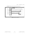
period1 and period2 specify the two periods making up the square wave to be generated. For
TC toggled output type and positive output polarity, period1 indicates the duration of the
on-cycle (high-logic state) and period2 indicates the duration of the off-cycle (low-logic
state).
Range: 1 through 65,535.
Using This Function
CTR_Square sets up the counter to generate a square wave of duration and frequency
determined by period1, period2, and timebase. If you specify no gating, the function
initiates square wave generation; otherwise, counter operation is controlled by the gate input.
The total period of the square wave is determined by the following formula:
(period1 + period2)
*
(timebase period)
This implies that the frequency of the square wave is as follows:
1/(period1 + period2)
*
(timebase period)
The percent duty cycle of the square wave is determined by the following formula:
period 1/(period1 + period2)
* 100%
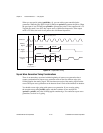
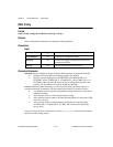
Figure 2-11 shows the timing of square wave generation for both TC toggled output and TC
pulse output. For this example, period1 = 3 and period2 = 2. The output signals shown are
positive polarity output signals.