


Chapter 2 Function Reference — DIG_SCAN_Setup
NI-DAQ FRM for PC Compatibles 2-190
©
National Instruments Corporation
Each output port also has a different Acknowledge Input (ACK*) control signal.
• PC6 on the I/O connector is for port 0.
• PC2 on the I/O connector is for port 1.
On the DIO-96 I/O connector, you can find four different sets of PC pins. They are APC, BPC,
CPC, and DPC. APC pins correspond to port 0 and port 1, BPC pins correspond to port 3 and
port 4, CPC pins correspond to port 6 and port 7, and DPC pins correspond to port 9 and port
10. For example, CPC7 is the Output Buffer Full (OBF) control signal for port 6 and CPC1 is
the Output Buffer Full (OBF) for port 7 if both ports are configured as handshaking output
ports.
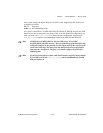
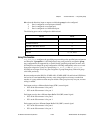
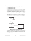
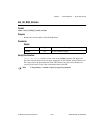
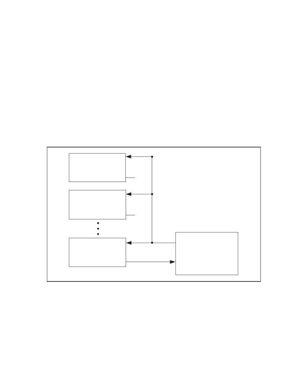
If a group of ports is configured as input, you need to tie all the corresponding Strobe Input
(STB*) together and connect them to the appropriate handshaking signal of the external
device. You should connect only the Input Buffer Full (IBF) of the last port on portList to
the external device. No connection is needed for the IBF of the other port on portList.
Figure 2-12.
Digital Scanning Input Group Handshaking Connections
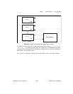
If a group of ports is configured as output, you should not make any connection on the control
signals except those for the last port on portList. You should make the connection with the
external device as if only the last port on portList is in the group. No connection is needed
for any other port on the list.
Port
x
1
STB*
External Device
(
last port in
p
ortList
)
Port
x
n
Port
x
2
STB*
STB*
IBF*
IBF*
IBF*