


Chapter 2 Function Reference — WFM_Load
NI-DAQ FRM for PC Compatibles 2-432
©
National Instruments Corporation
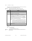
For each stage, Buffer ID [31:0] specifies the buffer number to be generated. This buffer ID
should correspond to one of the buffers that was loaded into the memory earlier by calling
WFM_Load
with mode = 3. If this is not the case, NI-DAQ then returns an error.
Sample Count [31:0] specifies the number of samples from the start of the buffer given by
Buffer ID. If this is set to 0, NI-DAQ uses the original size for that buffer specified during
WFM_Load
call with mode = 3. You can concatenate two consecutive buffers for generation
by specifying the Buffer ID of the first buffer and the Sample Count to be equal to the first
and following buffers. This feature allows flexibility to generate different waveforms from the
buffers already loaded into the memory.
Iterations [31:0] is used to specify the number of times you want to loop over the waveform
specified by the Buffer ID and Sample Count before jumping to the next stage. The valid
range of Iterations [31:0] is 1 to 65,536 for DAQArb 5411.
Marker Offset is equivalent to a trigger output signal. You can place a marker in every stage;
however, only one marker is allowed per stage. The marker is specified by giving a Marker
Offset [31:0] value (in number of samples) from the start of the waveform specified by the
stage. If the offset is out of range of the number of samples in that stage, the marker will not
appear at the output.
Note For information about staging-based waveform generation, refer to your NI-DAQ
User Manual for PC Compatibles.
Using This Function
WFM_Load
assigns your buffer to a selected analog output channel or channels. The values in
this buffer are translated to voltages by the D/A circuitry and produced at the output channel
when you have called
WFM_Group_Control
(operation = START) for a channel group. To
change the shape of a waveform in progress, use
WFM_DB_Config
to enable double-buffered
mode and
WFM_DB_Transfer
to transfer data into the waveform buffer. When loading
buffers for double-buffered mode, all of the channel buffers should be the same size.
WFM_Load
assigns your buffer to a selected analog output channel or channels. The values in
this buffer are translated to voltages by the digital-to-analog (D/A) circuitry and produced at
the output channel when you have called
WFM_Group_Control
(operation = START) for a
channel group. If you have changed the analog output configuration from the defaults by
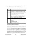
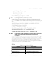
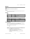
Iterations [31:16] ← Array element 4 (range 0 to 65,535)
Iterations [15:0] ← Array element 5 (range 0 to 65,535)
Marker Offset [31:16] ← Array element 6 (range 0 to 65,535)
Marker Offset [15:0] ← Array element 7 (range 0 to 65,535)
Table 2-43.
Array Structures for ARB Mode (Continued)