


Chapter 2 Function Reference — GPCTR_Set_Application
NI-DAQ FRM for PC Compatibles 2-236
©
National Instruments Corporation
are the low-to-high transitions of the signal on the PFI9/GPCTR0_GATE I/O connector
pin for general-purpose counter 0 and the PFI4/GPCTR1_GATE I/O connector pin for
general-purpose counter 1. The counter counts up starting from 0; its contents are placed in
the buffer after an edge of appropriate polarity is detected on the gate; the counter keeps
counting without interruption. NI-DAQ transfers data from the counter into the buffer until
the buffer is filled; the counter is disarmed at that time.
The counter width (24 bits) lets you count up to 2
24
– 1 events for E Series and 445X devices,
or up to 2
32
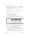
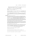
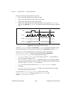
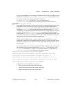
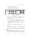
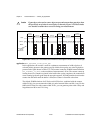
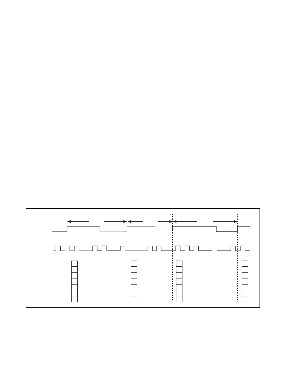
- 1 for the 6602 and 455X devices with counter width 32 bits. Figure 2-24 shows
one possible scenario of a counter used for
ND_BUFFERED_EVENT_CNT
after the following
programming sequence:
Make buffer be a 100-element array of u32.
GPCTR_Control(deviceNumber, gpctrNum, ND_RESET)
ND_RESET)
GPCTR_Set_Application(deviceNumber, gpctrNum, ND_BUFFERED_EVENT_CNT)
GPCTR_Config_Buffer(deviceNumber, gpctrNum, 0, 100, buffer)
GPCTR_Control(deviceNumber, gpctrNum, ND_PROGRAM)
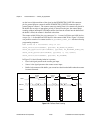
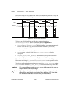
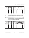
In Figure 2-24, the following behavior is present:
• Gate is the signal present at the counter gate input.
• Source is the signal present at the counter source input.
• Buffer is the contents of the buffer; you can retrieve data from the buffer when the counter
becomes disarmed.
Figure 2-24.
Buffered Event Counting
Source
Buffer
3
Gate
1 978
10 11
2
4
56
Counted
Events
Counted
Events
Counted
Events
4 4
6
4
6
11