


Chapter 2 Function Reference — DAQ_Start
©
National Instruments Corporation 2-137 NI-DAQ FRM for PC Compatibles
buffer is an integer array. buffer must have a length equal to or greater than count. The
elements of buffer are the results of each A/D conversion in the DAQ operation. This buffer
is often referred to as the acquisition buffer (or circular buffer when double-buffered mode is
enabled) elsewhere in this manual.
For DSA devices, buffer should be an array of i32. These devices return the data in a 32-bit
format in which the data bits are in the most significant bits.
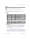
count is the number of samples to be acquired (that is, the number of A/D conversions to be
performed). For double-buffered acquisitions, count must be even.
Range: 3 through 2
32
– 1 (except Lab and 1200 Series devices that are not enabled for
doubled-buffered mode and the E Series devices)
3 through 65,535 (Lab and 1200 Series devices not enabled for double-buffered
mode).
2 through 2
24
(E Series devices).
2 through 2
24
– 3 (PCI-6110E and PCI-6111E). count must always be EVEN.
2 through 2
24
(PCI-445X).
2 through 2
32
– 1 (PCI-455X).
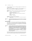
timebase is the timebase, or resolution, to be used for the sample-interval counter. timebase
has the following possible values:
–3: 20 MHz clock used as a timebase (50 ns) (E Series only).
–1: 5 MHz clock used as timebase (200 ns resolution) (AT-MIO-16F-5,
AT-MIO-64F-5, and AT-MIO-16X only).
0: External clock used as timebase (connect your own timebase frequency to the
internal sample-interval counter via the SOURCE5 input for MIO boards or, by
default, the PFI8 input for E Series devices).
1: 1 MHz clock used as timebase (1 µs resolution) (non-E Series MIO devices only).
2: 100 kHz clock used as timebase (10 µs resolution).
3: 10 kHz clock used as timebase (100 µs resolution) (non-E Series MIO devices
only).
4: 1 kHz clock used as timebase (1 ms resolution) (non-E Series MIO devices only).
5: 100 Hz clock used as timebase (10 ms resolution) (non-E Series MIO devices
only).
On E Series devices, if you use this function with the timebase set at 0, you must call
the function
Select_Signal with signal set to ND_IN_CHANNEL_CLOCK_TIMEBASE, and
source set to a value other than
ND_INTERNAL_20_MHZ and ND_INTERNAL_100_KHZ before
calling
DAQ_Start with timebase set to 0; otherwise, DAQ_Start will select low-to-high
transitions on the PFI 8 I/O connector pin as your external timebase.
Refer to the
Select_Signal function for further details about using the timebase with
E Series devices.