


Chapter 2 Function Reference — MIO_Calibrate
©
National Instruments Corporation 2-281 NI-DAQ FRM for PC Compatibles
Parameter Discussion
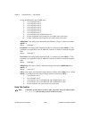
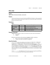
calOP determines the operation to be performed.
1: Load calibration constants from EEPROMloc.
2: Calibrate the ADC using internal reference voltage calibration constants in
refLoc.
3: Calibrate the DACs using internal voltage calibration constants in refLoc;
DAC0chan and DAC1chan are the analog input channels to which DAC0 and
DAC1 are connected, respectively.
4: Calibrate the internal reference voltage. You must connect a DC voltage of
calRefVolts to the analog input channel calRefChan. The calibration constants
are always stored in refLoc.
5: Copy ADC calibration constants from EEPROMloc to EEPROM load area.
6: Copy DAC calibration constants from EEPROMloc to EEPROM load area.
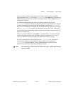
Note
(AT-MIO-16F-5 users only) When calOp is 3, you must connect each DAC to the
negative side of the respective input channel. Otherwise, the calibration will not
converge.
saveNewCal is only valid when calOP is 2 or 3.
0: Do not save new calibration constants in EEPROMloc.
1: Save new calibration constants in EEPROMloc.
EEPROMloc selects the storage location in the onboard EEPROM. You can use different sets
of calibration constants to compensate for configuration or environmental changes.
For the AT-MIO-16F-5:
1: User calibration area 1.
2: User calibration area 2.
3: User calibration area 3.
4: User calibration area 4.
5: User calibration area 5 (initial load area).
6: Factory calibration area (you cannot write into this area).
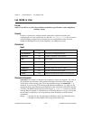
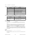
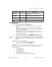
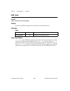
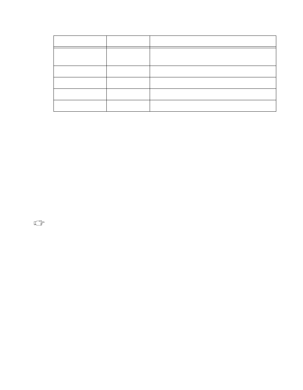
calRefChan i16 AI channel that the calibration voltage is
connected to
DAC0chan i16 AI channel that DAC0 is connected to
DAC1chan i16 AI channel that DAC1 is connected to
calRefVolts f64 DC calibration voltage
refLoc i16 source of the internal voltage reference constants
Name Type Description