


Chapter 2 Function Reference — CTR_Square
NI-DAQ FRM for PC Compatibles 2-112
©
National Instruments Corporation
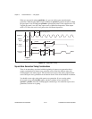
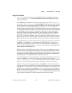
When you use special gating (gateMode = 8), you can achieve gate-controlled pulse
generation. When the gate input is high, NI-DAQ uses period1 to generate the pulses. When
the gate input is low, NI-DAQ uses period2 to generate the pulses. If the output mode is TC
Toggled, the result is two 50% duty square waves of difference frequencies. If the output
mode is TC Pulse, the result is two pulse trains of different frequencies.
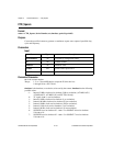
Figure 2-11.
Square Wave Timing
Square Wave Generation Timing Considerations
There is an uncertainty associated with the beginning of square wave generation due to
counter synchronization. Square wave generation starts on the first timebase edge after
NI-DAQ applies the starting signal. The time between receipt of the starting signal and the
start of the square wave generation can be between 0 and 1 units of the timebase in duration.
You should not use edge gating with square wave generation. If you use edge gating,
the waveform stops after period1 expires and then continues for one total period
(period2 + period1) only after NI-DAQ applies another edge. For continuous square wave
generation, use level or no gating.
0 < sync period < 1
1
Timebase
Starting
Signal
TC Toggle
Output
TC Pulse
Output
1
units = timebase period
1
period2
period2-1period1-1
period1