


Chapter 2 Function Reference — GPCTR_Set_Application
NI-DAQ FRM for PC Compatibles 2-226
©
National Instruments Corporation
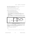
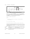
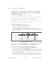
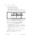
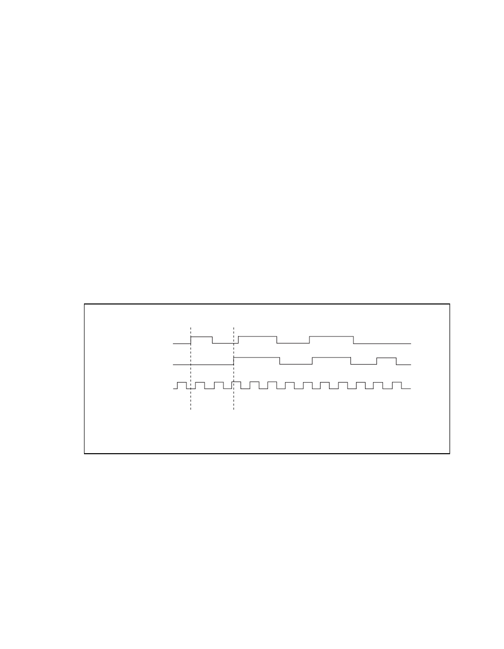
Figure 2-18 shows one possible use of a counter for
ND_TWO_SIGNAL_EDGE_SEPARATION_MSR after the following programming sequence:
GPCTR_Control (deviceNumber, gpctrNum, ND_RESET)
GPCTR_Set_Application (deviceNumber, gpctrNum,
ND_TWO_SIGNAL_EDGE_SEPARATION_MSR)
GPCTR_Control (deviceNumber, gpctrNum, ND_PROGRAM)
In Figure 2-18, the following behavior is present:
• Gate is the signal present at the counter gate input.
• Second Gate is the signal present at the counter second gate input.
• Source is the signal present at the counter source input.
• Count is the value you would read from the counter if you called the
GPCTR_Watch
function entityID =
ND_COUNT. The different numbers illustrate the behavior at different
times.
• Armed is the value you would read from the counter if you called the
GPCTR_Watch
function with entityID =
ND_ARMED. The different values illustrate behavior at different
times.
Figure 2-18.
Start-Stop Measurement
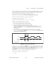
Use the GPCTR_Watch
function with entityID = ND_ARMED to monitor the progress of the
counting process. This measurement completes when entityValue becomes
ND_NO. When the
counter is no longer armed, you can retrieve the counted value by using
GPCTR_Watch with
entityID =
ND_COUNT, as shown in the following example code:
Create U32 variable counter_armed.
Create U32 variable counter_value.
repeat
Source
Count
Armed
3
Second Gate
Gate
10
YES YES YES
2
33
33
333
33
NO NO
NO NO
NO NO
NO NO