


Chapter 2 Function Reference — ICTR_Setup
©
National Instruments Corporation 2-253 NI-DAQ FRM for PC Compatibles
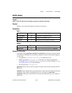
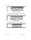
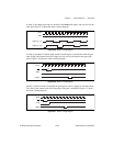
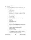
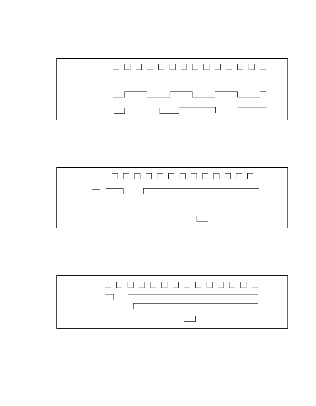
In mode 3, the output stays high for one half of the count clock pulses and stays low for the
other half. Figure 2-35 shows the mode 3 timing diagram.
Figure 2-35.
Mode 3 Timing Diagram
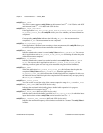
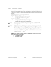
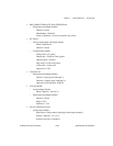
In mode 4, the output is initially high, and the counter begins to count down while the gate
input is high. On terminal count, the output goes low for one clock pulse, then goes high
again. Figure 2-36 shows the mode 4 timing diagram.
Figure 2-36.
Mode 4 Timing Diagram
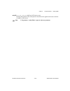
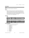
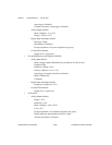
Mode 5 is similar to mode 4 except that the gate input is used as a trigger to reset the counter.
The value of the counter before the rising edge of the gate is undefined. Figure 2-37 shows
the mode 5 timing diagram.
Figure 2-37.
Mode 5 Timing Diagram
Clock
Gate
Output
Output
(n = 4)
(n = 5)
4
24242
42 4
2
42
45
4
25
2
5
42
5
2
5
42
Clock
WR
Gate
Output
n = 4
43 2 1 0
Clock
Gate
WR
Output
43 21 0
n = 2