


Chapter 2 Function Reference — Configure_HW_Analog_Trigger
NI-DAQ FRM for PC Compatibles 2-84
©
National Instruments Corporation
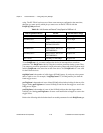
lowValue and highValue specify the levels you want to use for triggering. For E Series
devices, the legal range for the two values is 0 to 255 (0–4,095 for 16-bit boards). In addition,
lowValue must be less than highValue. The voltage levels corresponding to lowValue and
highValue are as follows:
• When trigSource =
ND_PFI_0, 0 corresponds to –10 V and 255 (4,095 for the 16-bit
boards) corresponds to +10 V; values between 0 and 255 (4,095 for 16-bit boards) are
distributed evenly between –10 V and +10 V. You can use
ND_PFI_0 as the analog signal
you are triggering off of at the same time you designate
ND_PFI_0 as a source for a
Select_Signal signal.
• When trigSource =
ND_THE_AI_CHANNEL and the channel is in bipolar mode, 0
corresponds to –5 V, 255 corresponds to +5 V; values between 0 and 255 are evenly
distributed between –5 V and +5 V. For 61XX devices, 0 corresponds to –10 V, 255
corresponds to 10 V.(For the 16-bit boards: 0 corresponds to –10 V, 4,095 corresponds to
+10 V, and values between 0 and 4,095 are evenly distributed between –10 V and +10 V.)
When trigSource =
ND_THE_AI_CHANNEL and the channel is in unipolar mode, 0
corresponds to 0 V, 255 (4,095 for the 16-bit boards) corresponds to +10 V; values
between 0 and 255 (4,095 for the 16-bit boards) are evenly distributed between 0 V and
+10 V.
See the end of this section for an example calculation for lowValue.
For DSA devices, the legal range for lowValue and highValue is –65,536 to +65,535. These
values correspond to the lower limit of the voltage range to the higher limit of the voltage
range for the current configuration of the trigger channel. For example, when the channel
is configured for 0 dB of gain, –65,536 corresponds to –10 V and +65, 535 corresponds to
+10 V.
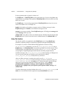
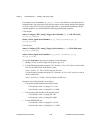
mode tells NI-DAQ how you want analog triggers to be converted into digital triggers that the
onboard hardware can use for timing.
Note The PCI-6110E and PCI-6111E can use any of the analog input channels for the
trigSource. For these devices set trigSource to the channel number you want,
instead of the constant
ND_THE_AI_CHANNEL
.
Note This also applies to the PCI-445X and PCI-455X devices.
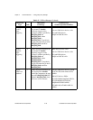
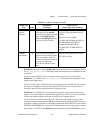
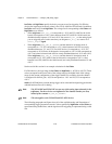
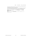
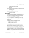
The following paragraphs and figures show all of the available modes and illustrations of
corresponding trigger generation scenarios. Values specified by highValue and lowValue are
represented using dashed lines, and the signal used for triggering is represented using a solid
line.