


Chapter 2 Function Reference — WFM_ClockRate
©
National Instruments Corporation 2-407 NI-DAQ FRM for PC Compatibles
0: If whichclock is equal to 0, the external clock is connected to OUT2 on the
MIO-16 and AT-MIO-16D; to EXTDACUPDATE* on the AT-MIO-16F-5,
AT-MIO-64F-5, and AT-MIO-16X; to EXTUPDATE on the AT-AO-6/10 and
Lab and 1200 Series analog output devices, or to a pin chosen through the
Select_Signal function on an E Series device (default is PFI5).
If whichclock is equal to 1, the external clock is connected to OUT2 on -the
AT-MIO-16X and AT-MIO-64F-5.
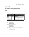
1: 1 MHz clock used as timebase (1 µs resolution) (Am9513-based devices only).
2: 100 kHz clock used as timebase (10 µs resolution).
3: 10 kHz clock used as timebase (100 µs resolution) (Am9513-based devices only).
4: 1 kHz clock used as timebase (1 ms resolution) (Am9513-based devices only).
5: 100 Hz clock used as timebase (10 ms resolution) (Am9513-based devices only).
6: SOURCE1 used as timebase (Am9513-based MIO devices only).
7: SOURCE2 used as timebase (Am9513-based MIO devices only).
8: SOURCE3 used as timebase (Am9513-based MIO devices only).
9: SOURCE4 used as timebase (Am9513-based MIO devices only).
10: SOURCE5 used as timebase (Am9513-based MIO devices only).
11: External timebase (E Series devices only).
Connect your external timebase to PFI5, by default, or use the
Select_Signal
function to specify a different source.
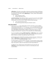
On the MIO-16/16D, timebase = 0 sets counter 2 to the high-impedance state, allowing its
output level to be externally driven by a signal connected to the OUT2 pin on the I/O
connector. On the Lab and 1200 Series analog output devices, timebase = 0 allows the signal
applied to the EXTUPDATE pin on the I/O connector to control the DAC update. On the
AT-AO-6/ 10, timebase = 0 allows the signal applied to the EXTDACUPDATE from the I/O
connector or RTSI bus to control the DAC update. On the AT-MIO-16F-5, AT-MIO-64F-5,
and AT-MIO-16X, timebase = 0 allows the signal applied to the EXTDACUPDATE pin on
the I/O connector to control the DAC update. Whenever an active low pulse is detected on one
of these pins, the DACs in the group are updated. When timebase = 0, the value of interval
is irrelevant. timebase = 1 through 5 selects one of the five available internal clock signals to
be used in determining the update interval.
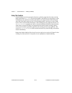
interval indicates the number of timebase units. If whichclock is 0, interval indicates the
number of timebase units of time that elapse between voltage updates at the analog output
channels in the group. If whichclock is 1, interval indicates the number of timebase units of
time that elapse after reaching the last point in DAC FIFO before the next cycle begins. If
whichclock is 2, interval indicates delay interval prescalar 1. If whichclock is 3, interval
indicates delay interval prescalar 2.
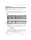
Range: 2 through 65,535 for the MIO devices and DAQArb 5411 devices, except for
E Series devices.
2 through 16,777,216 for E Series devices.