


Chapter 2 Function Reference — SCXI_Track_Hold_Setup
©
National Instruments Corporation 2-369 NI-DAQ FRM for PC Compatibles
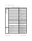
source indicates what signal controls the track/hold state of the module. If the inputMode
is 0, NI-DAQ ignores this parameter.
0: A counter of the DAQ device that is cabled to the module will be the source
(NI-DAQ will reserve and use Am9513-based device counter 2, an E Series
dedicated DAQ-STC counter, Lab and 1200 Series devices counter B1,
DAQCard-700 or LPM device counter 2 for this purpose). This source is only
valid if the module is cabled to a DAQ device.
1: An external signal connected to the HOLDTRIG pin on the front connector of
the module will control the track/hold state of the module. There is a hardware
connection between the HOLDTRIG pin and the counter output of the DAQ
device, so if source = 1 the appropriate counter (listed above) is driven by the
external signal and will be reserved. Keep in mind that if inputMode = 2, this
external signal will drive the scan interval timer. If you are using a Lab and 1200
Series devices, DAQCard-700, or LPM device, you must change the jumper
setting on the SCXI-1341 or SCXI-1342 adapter device to prevent the external
signal from damaging the timer chip on the DAQ device.
2: NI-DAQ will use a signal routed on an SCXIbus trigger line to control the
track/hold state of the module. If you are using an SCXI-1200 or the internal
connection to the SCXI backplane on the PXI-1010, you must use this option to
route the trigger signal from the backplane.
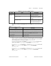
send indicates where else to send the signal specified by source for synchronization purposes.
NI-DAQ also ignores this parameter if the inputMode is 0.
0: Nowhere.
1: Make the source signal drive the DAQ device counter output and the
HOLDTRIG pin on the module front connector (if the source is not already one
of those signals). If you are using a DAQCard-700, DAQCard-1200,
Lab-PC-1200, Lab-PC-1200AI, Lab-PC+, PCI-1200, or LPM device, you must
change the jumper setting on the SCXI-1341 or SCXI-1342 adapter device to
prevent the external signal from damaging the timer chip on the DAQ device.
2: Make the source signal drive an SCXIbus trigger line so that other SCXI-1140
modules can use it (if the source is not from the SCXIbus). Only one SCXI-1140
module can drive that trigger line; an error will occur if you attempt to configure
more than one SCXI-1140 to drive it.
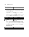
holdCount is the number of times the module is enabled by NI-DAQ during an interval scan
before going back into track mode. Each time Slot 0 encounters an entry for the module in the
module scan list, NI-DAQ enables the module, which remains enabled until the sample count
in that module scan list entry expires. If there is only one entry for the module in the module
scan list, holdCount should be 1 (this will almost always be the case).
Range: 1 to 255.