


Chapter 2 Function Reference — Calibrate_1200
NI-DAQ FRM for PC Compatibles 2-50
©
National Instruments Corporation
Caution Read the calibration chapter in your device user manual before using
Calibrate_1200.
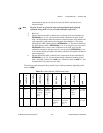
Parameters
Input
Parameter Discussion
calOP determines the operation to be performed.
1: Load calibration constants from EEPROMloc. If EEPROMloc is 0, the default
load table is used and NI-DAQ ensures that the constants loaded are appropriate
for the current polarity settings. If EEPROMloc is any other value you must
ensure that the polarity of your device matches those of the calibration constants.
2: Calibrate the ADC using DC reference voltage calRefVolts connected to
calRefChan. To calibrate the ADC, you must ground one input channel
(grndRefChan) and connect a voltage reference between any other channel and
AGND (pin 11). After calibration, the calibration constants that were obtained
during the process remain in use by the ADC until the device is initialized again.
Note The ADC must be in referenced single-ended mode for successful calibration of
the ADC.
3: Calibrate the DACs. DAC0chan and DAC1chan are the analog input channels
to which DAC0 and DAC1 are connected, respectively. To calibrate the DACs,
you must wrap-back the DAC0 out (pin 10) and DAC1 out (pin 12) to any two
analog input channels. After calibration, the calibration constants that were
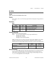
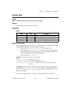
Name Type Description
device i16 device number
calOP i16 operation to be performed
saveNewCal i16 save new calibration constants
EEPROMloc i16 storage location on EEPROM
calRefChan i16 AI channel connected to the calibration voltage
grndRefChan i16 AI channel that is grounded
DAC0chan i16 AI channel connected to DAC0
DAC1chan i16 AI channel connected to DAC1
calRefVolts f64 DC calibration voltage
gain f64 gain at which ADC is operating
!