


Chapter 2 Function Reference — AO_Change_Parameter
©
National Instruments Corporation 2-33 NI-DAQ FRM for PC Compatibles
Output Attentuation
Some devices have attenuators after the final amplifier stage. By attenuating the output signal,
you do not lose any dynamic range of the signal; that is, you do not lose any bits from the
digital representation of the signal, because the attenuation is done after the DAC and not
before it.
Attenuation (in mdB) = - [20 log
10
(V
o
/V
i
)]*1000
V
o
= The voltage level that you want for the output signal.
V
i
= The input voltage level.
For DAQArb5411 devices, V
i
= -5 to +5 V for terminated load and -10 to +10 V for
unterminated load. For example, to change the output levels to –2.5 to +2.5 V into a
terminated load, then:
Attenuation = –[20*log
10
(
2.5/5)]*1000 = 6020 mdB
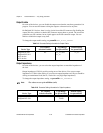
The 4451 and 4551 devices have three levels of attenuation providing voltage ranges of
–10 to + 10 V, –1 to +1 V, and –100 to +100 mV.
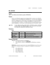
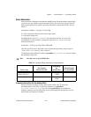
To change the output attenuation setting set paramID to
ND_ATTENUATION. You can change
the attenuation at any time.
Note
The values are set up in millidecibels.
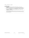
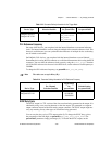
Frequency Correction for the Analog Filter
Some devices have an analog lowpass filter in their output stage. To correct for
the abnormalities of this filter at a particular frequency, set paramID to
ND_FILTER_CORRECTION_FREQ. You can set the paramValue to 0 to disable the
frequency correction for the analog filter. If you have disabled the analog filter, you also
must disable the frequency correction.
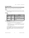
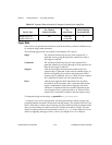
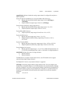
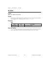
Table 2-11.
Parameter Setting Information for Output Attenuation
Device Type
Per Channel
Selection Possible
Legal Range
for
paramValue
Default Setting
for paramValue
DAQArb AT-5411
DAQArb PCI-5411
Yes 0 through
74,000
0
4451 and 4551 devices Ye s 0, 20,000,
40,000
0