


Chapter 2 Function Reference — GPCTR_Set_Application
NI-DAQ FRM for PC Compatibles 2-218
©
National Instruments Corporation
The following pseudo-code continuation of the example given earlier illustrates what
you can do to read the counter value continuously (
GPCTR_Watch function with
entityID =
ND_COUNT does this) and print it:
Repeat Forever
{
GPCTR_Watch(deviceNumber, gpctrNum, ND_COUNT, counterValue)
Output counterValue.
}
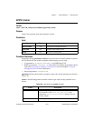
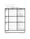
When the counter reaches terminal count (TC), it rolls over and keeps counting. To check if
this occurred, use
GPCTR_Watch function with entityID set to ND_TC_REACHED. Refer to
Table 2-32 for TC for E Series, 445X, 455X, and 6602 devices.
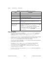
Typically, you will find modifying the following parameters through the
GPCTR_Change_Parameter function useful when the counter application is
ND_SIMPLE_EVENT_CNT. You can change the following:
•
ND_SOURCE to any value
•
ND_SOURCE_POLARITY to ND_HIGH_TO_LOW
• ND_INPUT_CONDITIONING (6602 and 455X devices only) to any value.
You can use the
GPCTR_Change_Parameter function after calling
GPCTR_Set_Application and before calling GPCTR_Control with
action =
ND_PROGRAM or ND_PREPARE.
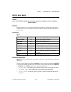
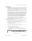
application =
ND_SINGLE_PERIOD_MSR
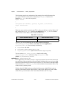
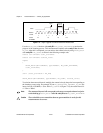
In this application, the counter is used for a single measurement of the time interval between
two transitions of the same polarity of the gate signal. By default, the events are low-to-high
transitions on the default gate connector pins (see Table 2-25). The counter counts the 20 MHz
internal timebase (
ND_INTERNAL_20_MHZ), so the resolution of measurement is 50 ns. The
counter counts up starting from 0.
With the default 20 MHz timebase, combined with the counter width (24 bits), you can
measure a time interval between 100 ns and 0.8 s long. For the 6602 devices with counter
width 32 bits, you can measure a time interval between 100 ns and 214 s long.
Table 2-32.
Terminal Count
E Series and 445X Devices 6602 and 455X Devices
2
24
– 1 2
32
– 1