3-13
1
2
3
4
2
6
7
8
3.3 Indexing
2) Devices with limits for use with index registers
Remark
For timer and counter present values, there are no limits on index register
numbers used.
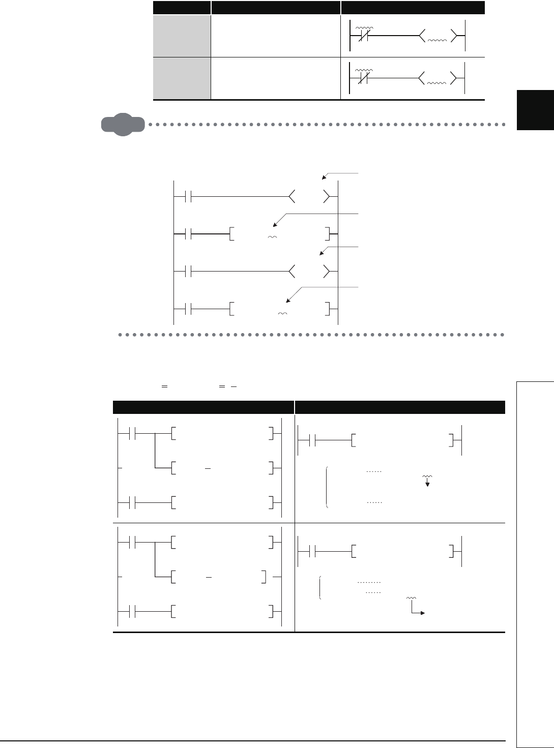
(c) A case where Indexing has been performed, and the actual process device, would be
as follows:
(When Z0 20 and Z1 5)
Fig. 3.7 Ladder Example and Actual Process Device
(3) Indexing with 32-bit (only Universal model QCPU)
A method of specifing index registers in indexing with 32-bit can be selected from the
following two methods.
• Specifing the index registers’ range used for indexing with 32-bit.
Device Meaning Application Example
T
• Only Z0 and Z1 can be used for
timer contacts and coils.
C
• Only Z0 and Z1 can be used for
counter contacts and coils.
Ladder Example Actual Process Device
T0Z0
T1Z1
K100
C0Z1
C1Z0
K100
SM400
Present value of timer
X0
Value set for timer
T0
K100
T0Z4K4Y30
BCD
SM400
Present value of counte
r
X1
Value set for counter
C100
K10
C100Z6K2Y40
BCD
X0
MOV K20 Z0
MOV K 5 Z1
X1
MOV K2X50Z0 K1M38Z1
Description
Converts K20 into a hexadecimal number.
X1
MOVK2X64
K1M33
K2X50Z0
K1M38Z1
K1M(38 - 5) = K1M33
K2X(50 + 14) = K2X64
X0
MOV K20 Z0
MOV K Z1
X1
MOV D0Z0 K3Y12FZ1
5
Description
Hexadecimal numbe
r
X1
MOV D20
K3Y12A
D
0Z0
K3Y12FZ1
D (0 + 20) = D20
K3Y(12F - 5) = K3Y12A


