7-181
CHKCIR,CHKEND
1
2
3
4
6
6
7
8
7.10 Debugging and failure diagnosis instructions
7.10.2 Changing check format of CHK instruction (CHKCIR,CHKEND)
(b) Failure checks check the ON/OFF status of OUT F by using the ladder pattern in the
various check conditions.
In all check conditions, SM80 will be turned ON if even one of the OUT F is ON in a
ladder pattern.
Further, the error numbers (contact numbers and coil numbers) corresponding to the
OUT F which were found to be ON will be stored from SD80 in BCD order.
(c) The instructions that can be used in ladder patterns are as follows:
Contacts ... LD, LDI, AND, ANI, OR, ORI, ANB, ORB, MPS, MPP,MRD, and
comparative operation instructions
Coil ........... OUT F
(d) The following devices can be used for ladder pattern contacts:
Input (X), Output (Y)
(e) Only annunciators (F) can be used in ladder pattern coils.
However, since annunciators (F) are used as a dummy, any value can be set for an
annunciator (F).
Further, they can overlap with no difficulties.
(f) ON/OFF controls can be performed without error if an annunciator (F) used during the
execution of the CHK instruction has the same number as an annunciator (F) used in
some other context than the CHK instruction. They will be treated differently during the
CHK instruction than they are in the different context.
(g) Since the annunciators (F) used in the CHK instruction do not turn ON/OFF actually,
they will not turn ON/OFF if monitored by a peripheral device.
(h) A ladder pattern can be created up to 256 steps.
Further, OUT F can use up to 9 coils.
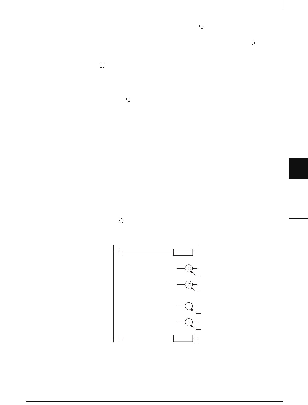
(3) Coil numbers for ladders designated with the CHKCIR through CHKEND instructions are
allocated coil numbers from 1 to 9, from top to bottom.
CHKCIR
SM400
CHKEND
SM400
Coil No. 1
Coil No. 9
Coil No. 2
Coil No. 8
F
F
F
F
to


