7-330
(SCL(P),DSCL(P))
7.13.4 Scaling (Point-by-point coordinate data) (SCL(P),DSCL(P))
(SCL(P),DSCL(P))
Function
)
SCL(P)
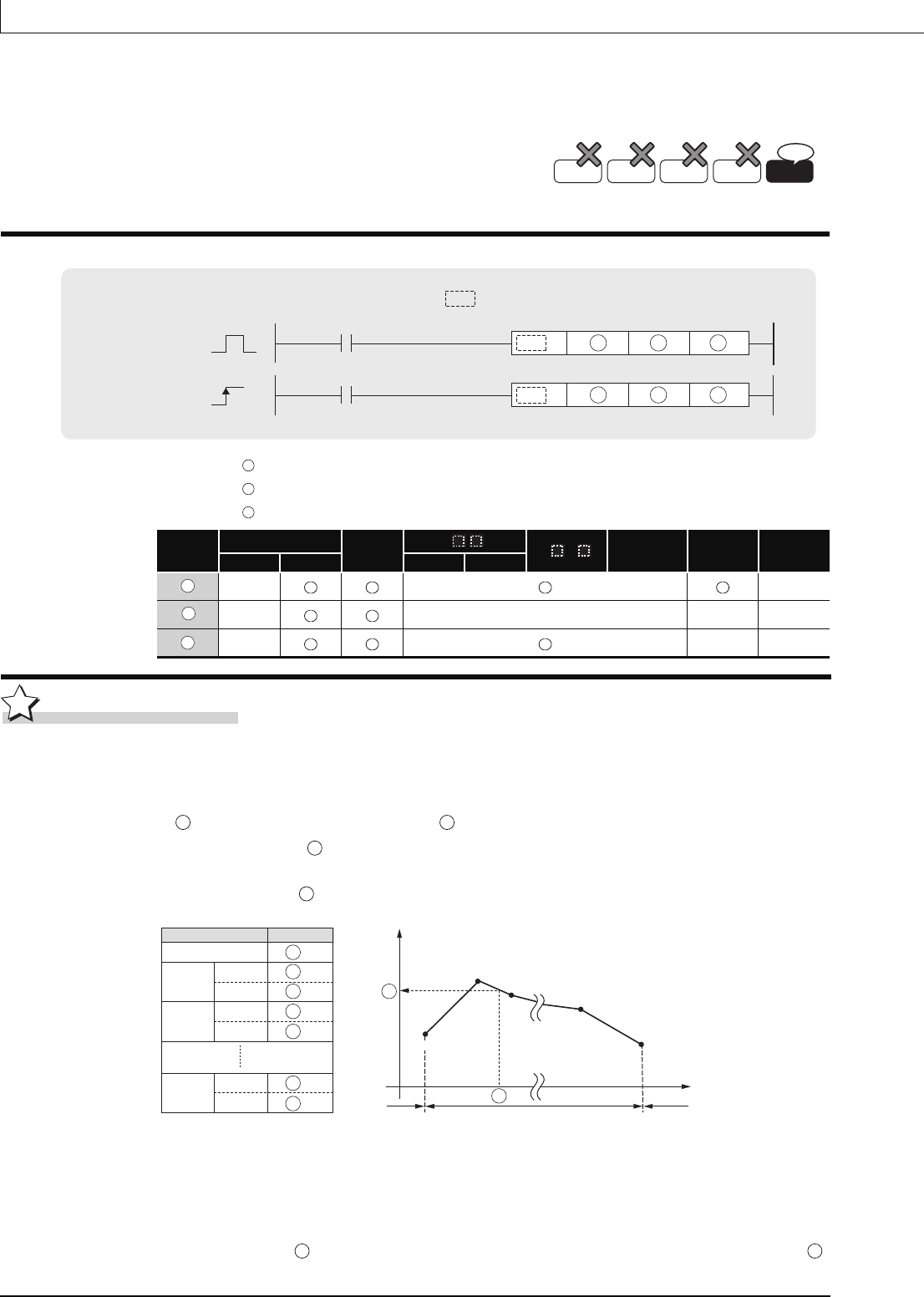
(1) This instruction executes scaling for the scaling conversion data (16-bit data units) specified
by with the input value specified by , and then stores the operation result into the
devices specified by .
The scaling conversion is executed based on the scaling conversion data stored in the
device specified by and up.
(2) If the value does not result in an integer, this instruction rounds the value to the whole
number.
(3) Set the X coordinate of the scaling conversion data in ascending order.
(4) Set the input value within the range of the scaling conversion data (within the range of
devices).
QnU(D)(H)CPU: The serial number (first five digits) is "10102" or later.
QnUDE(H)CPU: The serial number (first five digits) is "10102" or later.
: Input values for scaling or head number of the device where input values are stored(BIN 16/32 bits)
: Head number of the devices where scaling conversion data are stored(BIN 16/32 bits)
: Head number of the devices where output values depending on scaling are stored(BIN 16/32 bits).
Setting
Data
Internal Devices
R, ZR
J\
U\G
Zn
Constants
K, H
Other
Bit Word Bit Word
–– ––
–– –– –– ––
–– –– ––
Basic
Process
High
performance
Redundant
Ver.
Universal
SCL.DSCL
D
S2S1
SCLP.DSCLP
D
P
S2S1
Command
Command
indicates an instruction symbol of
SCL/DSCL.
S1
S2
D
S1
S2
D
S2
S1
D
S2
Scaling conversion data component
Setting item
Device assignment
Number of coordinate points
Point 1
X coordinate
Y coordinate
X coordinate
Y coordinate
Point 2
X coordinate
Y coordinate
Point n
S2
S2 1
S2 2
S2 3
S2 4
S2 2n 1
S2 2n
Y
Output
value
D
Input value S1
Point 2
Point 3
Point n 1
Point n
Point 1
X
Operable range Operation erro
r
Operation error
n indicates the number of coordinates
specified by (S2).
S1
S2


