7-51
SFTBR(P),SFTBL(P)
1
2
3
4
6
6
7
8
7.3 Shift instruction
7.3.3 n-bit shift to right or left of n-bit data (SFTBR(P),SFTBL(P))
7.3.3 n-bit shift to right or left of n-bit data (SFTBR(P),SFTBL(P))
SFTBR(P),SFTBL(P)
*1 : T, C, ST, and S devices are not available.
Function
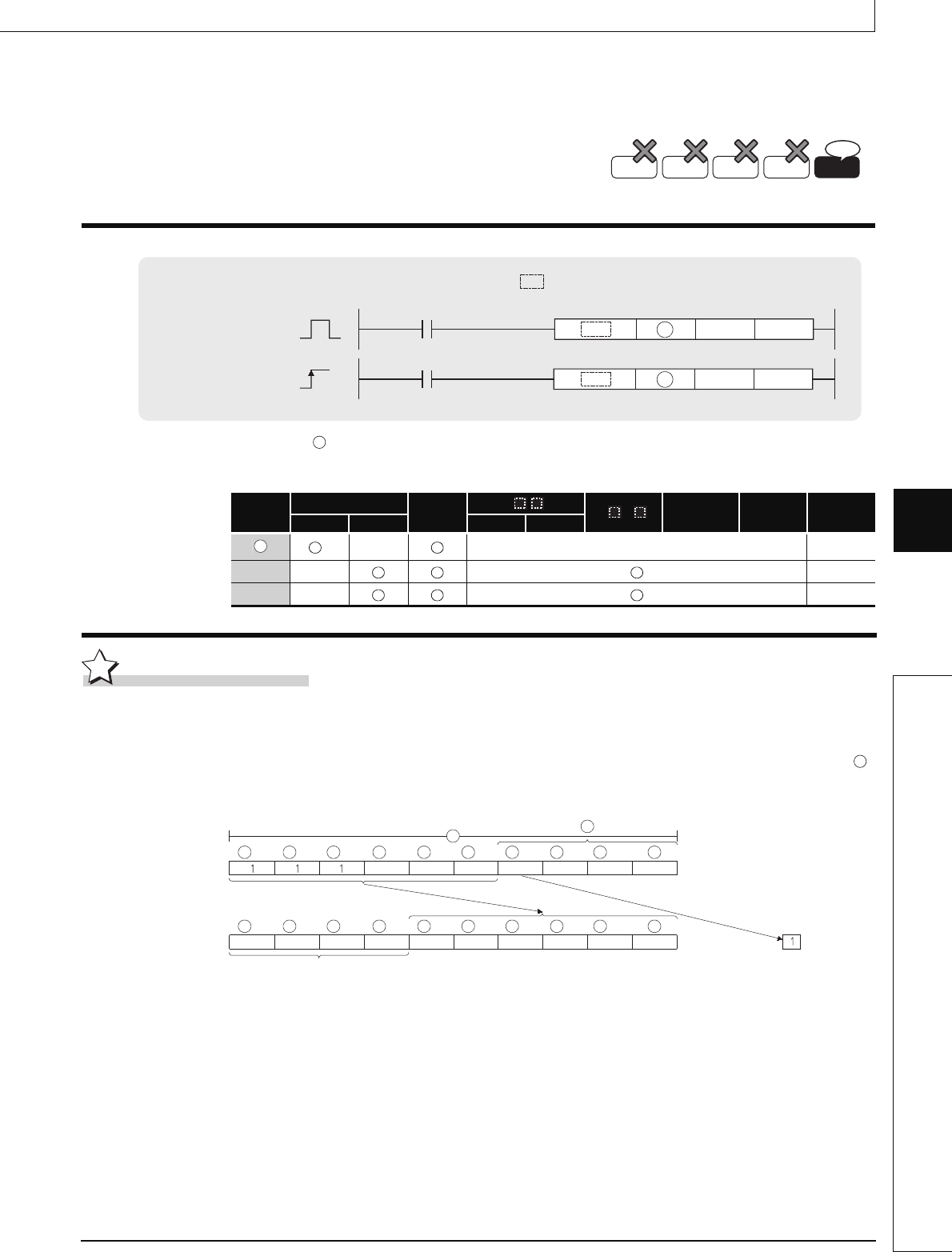
SFTBR(P)
(1) This instruction shifts the n1 bits data in the devices starting from the device specified by
to the right by n2 bits.
n1=10, n2=4
(2) n1 and n2 are specified under the condition that n1 is larger than n2. If the value of n2 is
equal to or larger than the value of n1, the remainder of n2 / n1 (n2 devided by n1) is used
for a shift.
(3) This instruction specifies n1 ranged from 1 to 64.
(4) Bits starting from the highest bit to n2th bit are filled with 0s. If the value of n2 is larger than
the value of n1, the remainder of n2 / n1 will be 0.
(5) If the value specified by n1 or n2 is 0, the instruction will be not processed.
QnU(D)(H)CPU: The serial number (first five digits) is "10102" or later.
QnUDE(H)CPU: The serial number (first five digits) is "10102" or later.
: Head number of the devices to be shifted (bits)
n1 : Number of bits to be shifted (BIN 16 bits)
n2 : Number of shifts (BIN 16 bits)
Setting
Data
Internal Devices
R, ZR
J\
U\G
Zn
Constants
K, H
Other
Bit Word Bit Word
*1
–– –– ––
n1 –– ––
n2 –– ––
Basic
Process
High
performance
Redundant
Ver.
Universal
Command
Command
SFTBR,SFTBL
SFTBRP,SFTBLP
P
n2
n2
D
n1
n1
D
indicates an instruction symbol of SFTBR/SFTBL.
D
D
D
Filled with 0s
2
1
3456789
Carry flag
(SM700)
n1
n2
DDDD DDDDDD
D
D
DDDDDDDD
00 0 0
01
11 1 1
111
1
00
0
2
13456789
