6-51
ED+(P),ED-(P)
1
2
3
4
4
6
7
8
6.2 Arithmetic Operation Instructions
6.2.10 Addition and subtraction of floating decimal point data (Double precision) (ED+(P),ED-(P))
ED-
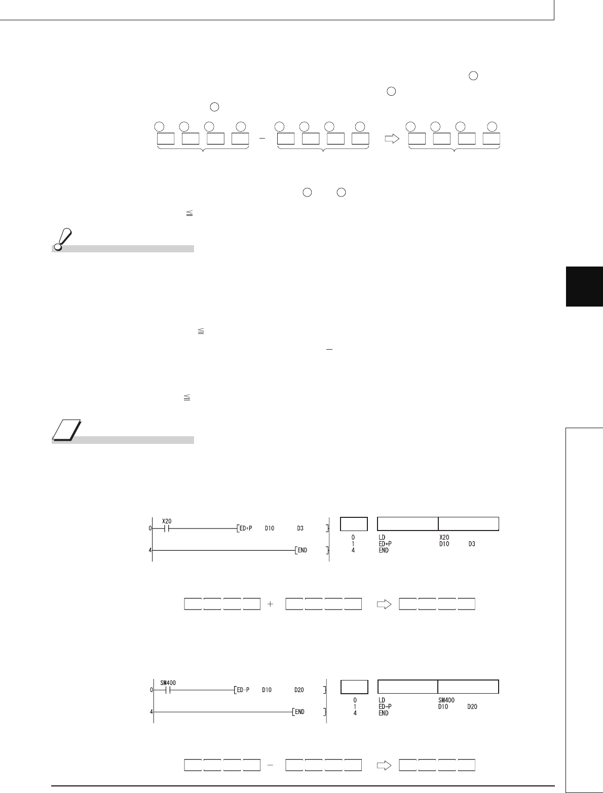
(1) Subtracts a 64-bit floating decimal point type real number designated by and a 64-bit
floating decimal point type real number designated by , and stores the result at a device
designated by .
(2) Values which can be designated at and and which can be stored, are as follows:
0, 2
-1022
| Designated value (stored value) | < 2
1024
Operation Error
(1) In any of the following cases, an operation error occurs, the error flag (SM0) turns ON, and
an error code is stored into SD0.
• The contents of the designated device or the result of the addition are not "0", or not within
the following range: (Error code: 4140)
0, 2
-1022
| Contents of designated device | < 2
1024
• The value of the designated device is 0. (Error code: 4140)
• The result of addition/subtraction exceeds the following range (Operation results in an
overflow):
2
1024
| Result of operation | (Error code: 4141)
Program Example
(1) The following program adds the 64-bit floating decimal point type real numbers at D3 to D6
and the 64-bit floating decimal point type real numbers at D10 to D13 when X20 goes ON,
and stores the result at D3 to D6.
[Ladder Mode] [List Mode]
[Operation]
(2) The following program subtracts the 64-bit floating decimal point type real number at D10 to
D13 from the 64-bit floating decimal point type real numbers at D20 to D23, and stores the
result of the subtraction at D20 to D23.
[Ladder Mode] [List Mode]
[Operation]
D
S
D
+3
64-bit floating-point
real number
D
+2
D
D
+1
D
+3
64-bit floating-point
real number
S
+2
S
S
+1
S
+3
64-bit floating-point
real number
D
+2
D
D
+1
D
S
D
Step
Instruction
Device
D4
5961.437
D3D6 D5
D11
12003.200
D10D13 D12
D4
17964.637
D3D6 D5
Step
Instruction
Device
D21
97365.203
D20D23 D22
D11
76059.797
D10D13 D12
D21
21305.406
D20D23 D22


