7-173
LEDR
1
2
3
4
6
6
7
8
7.9 Display instructions
7.9.3 Error display and annunciator reset instruction (LEDR)
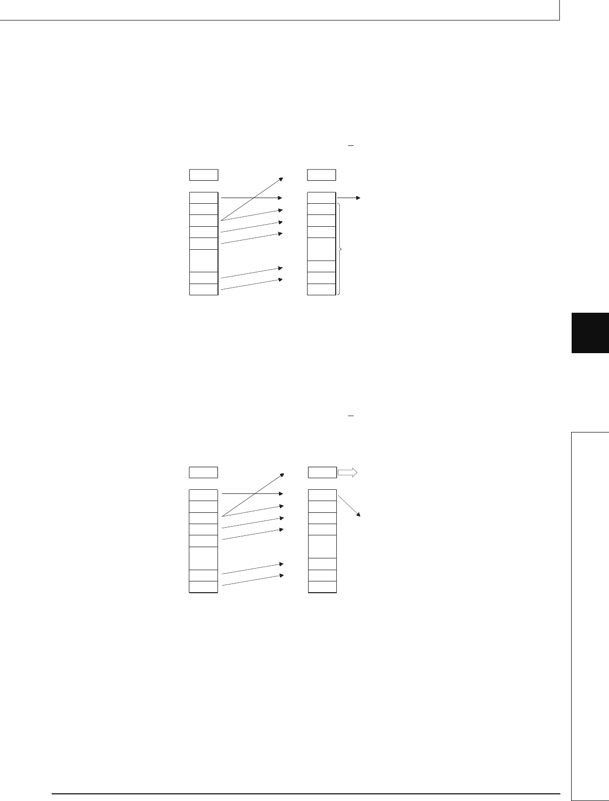
(2) Operations when an annunciator (F) is ON.
(a) When the CPU module has no LED display
The following operations will be conducted when the LEDR instruction is executed:
1) "USER" LED flickers, and is turned OFF
2) The annunciators (F) stored in SD62 and SD64 are reset, and the F numbers for
SD65 to SD79 are moved up.
3) The data newly stored at SD64 is transmitted to SD62.
4) The data at SD63 is decremented by 1. However, if SD63 is 0, it remains 0.
(b) For CPUs with an LED display at the front
The following operations will be conducted when the LEDR instruction is executed:
1) The F number being displayed at the front of the CPU module will be reset.
2) "USER" LED flickers, and is turned off.
3) The annunciators (F) stored in SD62 and SD64 are reset, and the F numbers for
SD65 to SD79 are compressed forwards.
4) The data newly stored at SD64 is transmitted to SD62.
5) The data at SD63 is decremented by 1. However, if SD63 is 0, it remains 0.
6) The F number being stored at SD62 is displayed at the LED display. However, if the
value of SD63 is 0, nothing will be displayed.
Before execution
200
15
200
99
5
255
83
0
SD62
SD63
SD64
SD65
SD66
SD67
SD78
SD79
After execution
99
14
99
5
255
83
0
0
SD62
SD63
SD64
SD65
SD66
SD77
SD78
SD79
F number storage area
Number of registered F numbers
Decrements 1.
Decrements 1.
Before execution
200
1
200
0
0
0
0
0
SD62
SD63
SD64
SD65
SD66
SD67
SD78
SD79
After execution
0
0
0
0
0
0
0
0
SD62
SD63
SD64
SD65
SD66
SD77
SD78
SD79
Number of registered F numbers
F number is not displayed on the
LED display unit since SD63 is 0.


