6-83
INT(P),DINT(P)
1
2
3
4
4
6
7
8
6.3 Data conversion instructions
6.3.5
Conversion from floating decimal point data to BIN16- and 32-bit data (Single precision)
(INT(P),DINT(P))
6.3.5 Conversion from floating decimal point data to BIN16- and
32-bit data (Single precision) (INT(P),DINT(P))
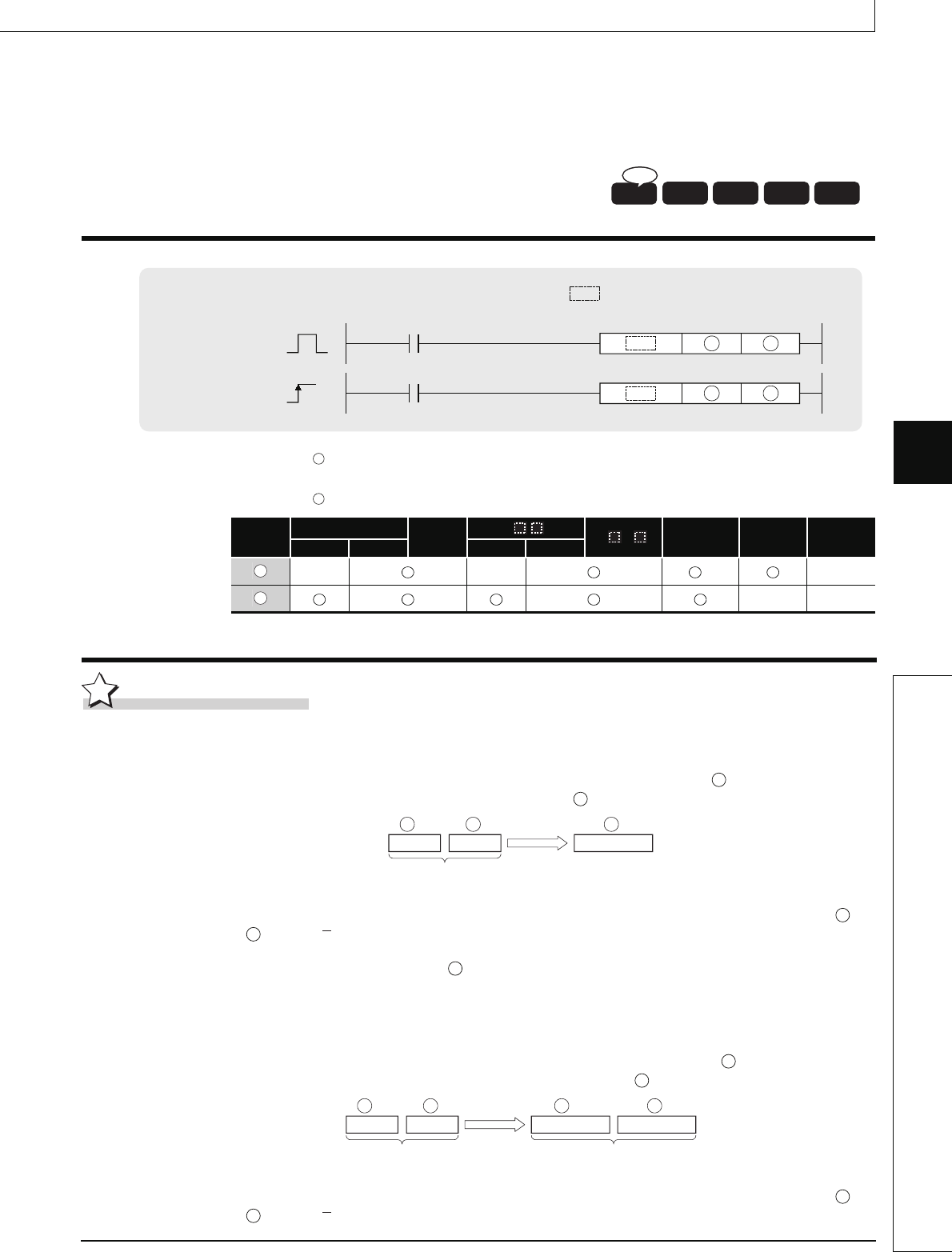
INT(P),DINT(P)
*1:Available only in multiple Universal model QCPU
Function
INT
(1) Converts the 32-bit floating decimal point real number designated at into BIN 16-bit data
and stores it at the device number designated at .
(2) The range of 32-bit floating decimal point type real numbers that can be designated at +1
or is from 32768 to 32767.
(3) Stores integer values stored at as BIN 16-bit values.
(4) After conversion, the first digit after the decimal point of the real number is rounded off.
DINT
(1) Converts 32-bit floating decimal point type real number designated by to BIN 32-bit data,
and stores the result at the device number designated by .
(2) The range of 32-bit floating decimal point type real numbers that can be designated at +1
or is from 2147483648 to 2147483647.
Basic model QCPU: The upper five digits of the serial No. are "04122" or larger.
: 32-bit floating decimal point data to be converted to BIN value or head number of the devices where the
floating decimal point data is stored (real number)
:
Head number of the devices where the converted BIN value will be stored (BIN 16/32 bits)
Setting
Data
Internal Devices
R, ZR
J\
U\G
Zn
Constants
E
Other
Bit Word Bit Word
–– ––
*1
––
–– ––
Process
High
performance
Redundant
Universal
Ver.
Basic
P
Command
Command
S D
S D
INT, DINT
INTP, DINTP
indicates an instruction symbol of INT/DINT.
S
D
S
D
S
D
BIN16-bit
32-bit floating-point
real number
+1
S S D
S
S
D
S
D
BIN 32 bits
Lower 16 bitsUpper 16 bits
32-bit floating-point
real number
+1
S
+1
DS D
S
S


