3-38
2) Except Instructions applicable to subset processing
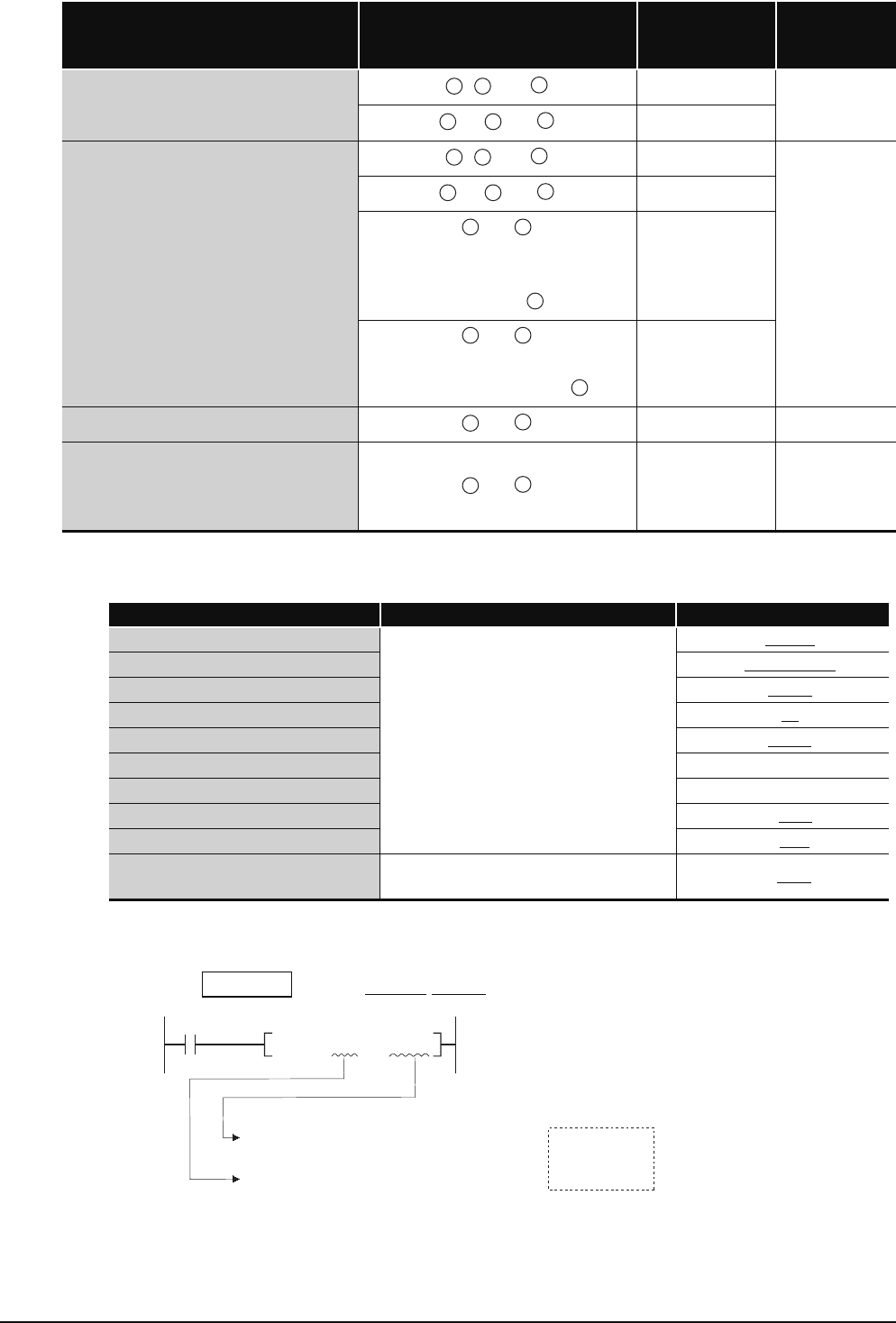
The following table shows steps depending on the devices.
(d) In cases where the conditions described in (a) to (c) above overlap, the number of steps
becomes a culmination of the two.
MOV If U1
\G10 ZR123 has been designated, a total of 2 steps are added.
Instruction Symbols
Locations Where Standard Device Regis-
ter Is Used
Added Steps
(Number of
Instruction Steps)
Basic Number of
Steps
*, *P, /, /P
, , and
-2(1)
3
, or and
-1(2)
D*, D*P, D/, D/P, E*, E*P
, , and
-2(1)
3
, or and
-1(2)
and
(only when that device that the
number of steps does not increase is
specified for )
±0(3)
and
(only when a serial number access format
file register is specified for )
+2(5)
MOV,MOVP,DMOV,DMOVP,EMOV,EMOVP
and
-1(1) 2
BCD,BCDP,BIN,BINP,DBCD,DBCDP,
DBIN,DBINP,FLT,FLTP,DFLT,DFLTP,
INT,INTP,DINT,DINTP,CML,CMLP,
DCML,DCMLP
and
-1(1) 2
Devices with Additional Steps Added Steps Example
Intelligent function module device
1
MOV U4\G10
D0
Multiple CPU shared device
MOV U3E1\G10000 D0
Link direct device
MOV J3\B20 D0
Index register / standard device register
MOV Z0 D0
Serial number access format file register
MOV ZR123 D0
Extended data register(D)
MOV D123
Extended link register(W)
MOV W123
32-bit constant
DMOV K123 D0
Real constant
EMOV E0.1 D0
Character string constant
For even number: (number of characters) / 2
For odd numbers: (number of characters + 1) / 2
$MOV "123" D0
Example
MOV
U1
\
G10 ZR123
Serial number access format file registers
Intelligent function module devices
Increased by 2 steps
+
=
: 1 step
: 1 step


