


SPI-4.2 Lite v4.3 User Guide www.xilinx.com 119
UG181 June 27, 2008
Source Clocking Options
R
The clock implementation for SysClk and TSClk is selected in the CORE Generator GUI.
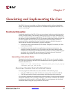
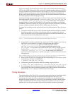
Depending on the chosen clocking option, different clock resources will be used. Table 6-3
and Table 6-4 provide the clocking resource count for each clocking option.
Slave Clocking
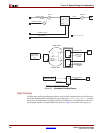
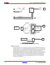
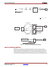
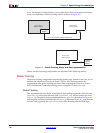
The Source slave clocking configuration allows users to fully customize the way the Source
core clocks are implemented. When implementing multiple SPI-4.2 Lite cores in a single
device, the user can have one master clocking SPI-4.2 Lite core which provides the clocking
for all Source slave clocking cores. The user can also implement a single slave-clocking
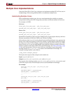
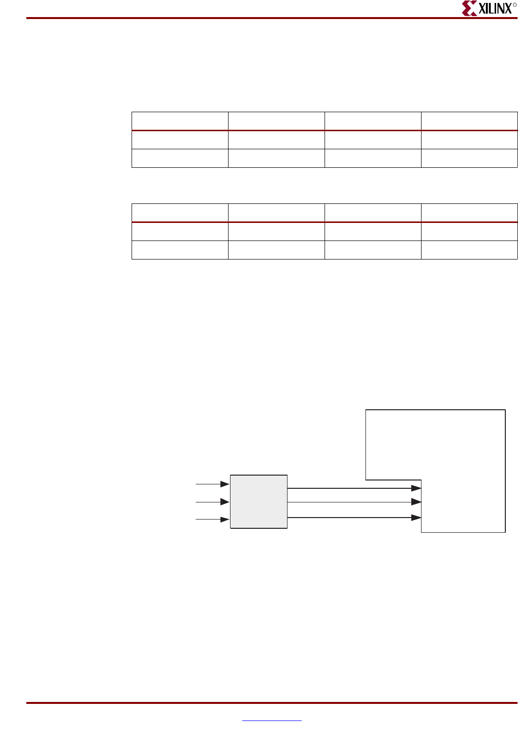
module that can be used to drive the clocks for all Source cores. An example file is
provided (pl4_lite_src_clk.v/.vhd) to demonstrate how to implement a clocking module
for the Source core. An illustration of the Slave clock inputs and this example module are
shown in Figure 6-10 and the inputs are defined in Table 2-18, page 41.
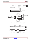
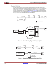
The clocking implementation in the example file provided (pl4_lite_src_clk.v/.vhd) is
customized based on the user selected parameters in the Coregen GUI. The global or
regional selections for SysClk and TSClk will be reflected in this slave clocking example
file. The implementations of global and regional clocking provided in the example file are
identical to the internal implementations described in the master clocking section.
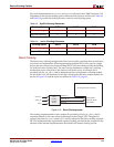
Table 6-3: SysClk Clocking Resources
Clocking Option BUFR BUFG DCM
Global Clocking 0 1 1
Regional Clocking 1 0 0
Table 6-4: TSClk Clocking Resources
Clocking Option BUFR BUFG DCM
Global Clocking 0 1 0
Regional Clocking 1 0 0
Figure 6-10: Slave Clocking Inputs
Slave
Clocking
Example
Module
SysClk_P
SysClk_N
TSClk
SysClk0_buf
SysClk180_buf
TSClk_buf
SysClk0_GBSLV
SysClk180_GBSLV
TSClk_GBSLV
SPI-4.2 Lite Source Core
(Configured with Slave Clocking)