


126 www.xilinx.com SPI-4.2 Lite v4.3 User Guide
UG181 June 27, 2008
Chapter 7: Simulating and Implementing the Core
R
In the first method, when defining the initial values of the calendar block RAM using a
COE file, the CORE Generator system converts the calendar sequence defined in the COE
file into calendar block RAM constraints in the example UCF file. During implementation,
the UCF calendar constraints are used to initialize the Sink and Source calendar block
RAM content with the desired sequence. However, the functional simulation files must be
manually updated to reflect this programming.
Note that the following steps only apply to a Sink or Source gate-level simulation model
delivered in the SPI-4.2 Lite release (the <component_name>_pl4_lite_snk_top.vhd
or <component_name>_pl4_lite_src_top.vhd or similar files). If the complete
loopback design is run through NGDBuild, or the complete user design is run through
NGDBuild, followed by running the netgen, the gate-level netlist will already contain the
correctly initialized calendar sequence, and no further steps are required.
To change the simulation models to match the physical implementation, follow the steps
below.
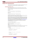
1. Generate or modify the top-level UCF files that contain the Sink and Source calendar
initialization values. An example of a 4-channel Sink core configuration is shown
below for the SPI-4.2 Lite core (note that unused entries can either be initialized to 0, or
left unused, which will also default the values to 0):
INST”<component_name>_pl4_lite_snk_top0/pl4_lite_snk_core0/pl4_lite_snk_cal0/CalRAM/BlockRam”
INIT_00 = 0000000000000000000000000000000000000000000000000000000003020100;
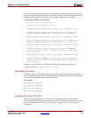
2. Copy the UCF calendar constraints into a temporary UCF file using the same name as
the SPI-4.2 Lite core netlist. For example, if the generated sink netlist is
ch4_pl4_lite_snk_top.ngc, the new UCF file should be named
ch4_pl4_lite_snk_top.ucf. The calendar initialization portion of the
pl4_wrapper.ucf should then be copied into this new UCF file, and the top-level
instance name (<component name>pl4_lite_snk_top0/ for the Sink Core,
<component_name>pl4_lite_src_top0/ for the Source Core) needs to be
removed. For the example above, “pl4_lite_snk_top0/” would be removed so that the
file appears as:
INST”<component_name>_pl4_lite_snk_top0/pl4_lite_snk_core0/pl4_lite_snk_cal0/CalRAM/BlockRam”
INIT_00 = 0000000000000000000000000000000000000000000000000000000003020100;
3. Make sure the SPI-4.2 Lite core netlist and the corresponding new UCF files are in the
same directory, and then run NGDBuild:
> ngdbuild ch4_pl4_lite_snk_top
4. Generate the gate-level simulation netlist by running netgen as follows:
> netgen -sim -ofmt <vhdl|verilog> -xon false ch4_pl4_lite_snk_top.ngd
5. The resulting gate-level simulation netlist will contain the calendar sequence load
logic. Replace the gate-level netlists (created by the CORE Generator system) that are
located in the <proj>/directory with the output from netgen.
Timing Simulation
Timing simulation of the SPI-4.2 Lite core is performed on the post-par simulation model
after the core and the user design are implemented through the Xilinx tools. This
simulation will provide not only a cycle-accurate simulation, but also model how the
design will operate in hardware. The SPI-4.2 Lite core has been verified with the Mentor
Graphics ModelSim PE/SE/EE simulator. While other simulation tools can be used to
simulate the core, they have not been tested and functionality cannot be guaranteed.