


SPI-4.2 Lite v4.3 User Guide www.xilinx.com 23
UG181 June 27, 2008
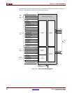
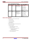
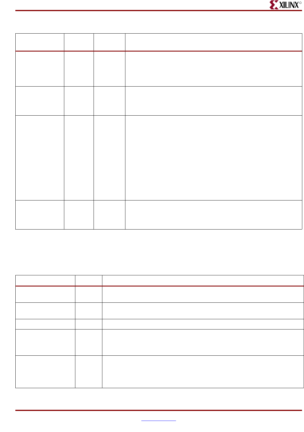
Sink Core Interfaces
R
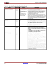
Sink FIFO Interface
The Sink FIFO Interface signals allow you to access the data (received on the SPI-4.2
Interface) that is stored in the FIFO. The signals on this interface is defined in Table 2-3.
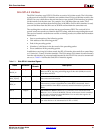
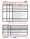
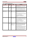
SnkOof Output SnkFFClk Sink Out-of-Frame: Active high signal that indicates that the SPI-4.2 Lite
Sink block is not in frame. This signal is asserted when SnkEn is deasserted
or the Sink block loses synchronization with the data received on the SPI-4.2
Interface. This signal is deasserted once the Sink block reacquires
synchronization with the received SPI-4.2 data.
SnkBusErr Output SnkFFClk Sink Bus Error: Active high signal that indicates SPI-4.2 protocol violations
or bus errors that are not associated with a particular packet. Information on
the specific error condition that caused the SnkBusErr assertion is provided
on SnkBusErrStat
SnkBusErrStat[7:0] Output SnkFFClk Sink Bus Error Status: Each bit of this bus corresponds to a specific Sink Bus
Error condition and is asserted concurrently with SnkBusErr. The error
conditions detected are reported as follows:
SnkBusErrStat [0]: Minimum SOP spacing violation
SnkBusErrStat [1]: Control word with EOP not preceded by a data word
SnkBusErrStat [2]: Payload control word not followed by a data word
SnkBusErrStat [3]: DIP4 error received during training or on idles
SnkBusErrStat [4]: Reserved control words received
SnkBusErrStat [5]: Non-zero address bits on control words received (except
on payload and training control words)
SnkBusErrStat [6:7]: Reserved bits (tied low)
SnkTrainValid Output SnkFFClk Sink Training Valid: Active high signal that indicates that a valid training
pattern has been received. This signal is asserted for the duration of the
training pattern (20 SPI-4.2 bus clock cycles or 5 RDClk0_GP clock cycles), if
the training pattern received is successfully decoded.
Table 2-2: Sink Control and Status Signals (Continued)
Name Direction
Clock
Domain
Description
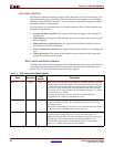
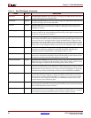
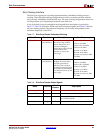
Table 2-3: Sink FIFO Signals
Name
Direction
Description
SnkFFClk Input Sink FIFO Clock: All Sink FIFO Interface signals are synchronous to the rising edge of
this clock.
SnkFFRdEn_n Input Sink FIFO Read-Enable: When detected low at the rising edge of SnkFFClk, data and
status information is available from the FIFO on the next rising edge of SnkFFClk.
SnkFFAddr[7:0] Output Sink FIFO Channel Address: Channel number associated with the data on SnkFFData.
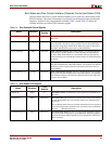
SnkFFData[31:0]
or
SnkFFData[63:0]
Output Sink FIFO Data Out: The Sink FIFO data bus. Bit 0 is the LSB.
The core can be configured to have a 32- or 64-bit Interface. The 64-bit interface enables
running at half the clock rate required for a 32-bit interface.
SnkFFMod[1:0]
or
SnkFFMod[2:0]
Output Sink FIFO Modulo: This signal indicates which bytes on the SnkFFData bus are valid
when the SnkFFEOP signal is asserted.
SnkFFMod[1:0] is used with a 32-bit interface.
SnkFFMod[2:0] is used with a 64-bit interface.