


54 www.xilinx.com SPI-4.2 Lite v4.3 User Guide
UG181 June 27, 2008
Chapter 4: Designing with the Core
R
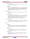
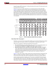
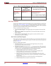
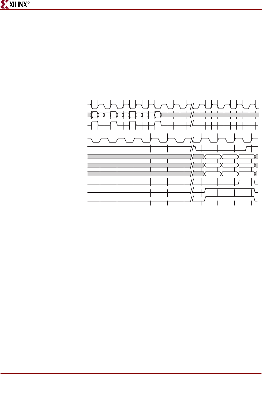
channel 2 and an SOP for channel 1, followed by three 16-bit words. The last control word
(C4) is an EOP for channel 1.
The data received on the SPI-4.2 Interface is processed and stored in the Sink FIFO.
Figure 4-1 also shows the data being read out of the FIFO and uses forward slashes to
indicate that there is latency in processing and storing the SPI-4.2 data. The first 64-bit
word on the FIFO interface contains the two 16-bit words received for channel 1 with an
EOP. The second 64-bit word contains the two words received for channel 2 with an EOP.
The last 64-bit word on the FIFO interface contains the three words written for channel 1.
When the last word is read out of the FIFO, both the SnkFFSOP and SnkFFEOP for channel
1 are asserted.
Sink Data Path: Example 2
The Sink core automatically and optimally handles any size packet including short packets
(less than eight cycles apart), which have multiple SOPs or payload control words.
There are two scenarios in which short packets can be received:
• Received SOPs that are less than eight cycles apart. Data is passed through the core
as received and a SnkBusErr is flagged, indicating a protocol violation.
• Received Payload Control words that are less than eight cycles apart. Though the
SPI-4.2 specification requires that successive SOPs must occur not less than eight
cycles apart, there is no restriction on payload control words, which are not SOPs. The
Sink core can process single payload control words followed by single data words
(CTL-DATA-CTL-DATA-CTL, etc.). Because this is not a protocol violation, no
SnkBusErr is asserted.
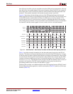
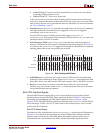
Figure 4-2 shows the transfer of short packets from the SPI-4.2 Interface through the Sink
FIFO to the 64-bit user interface. Because each packet contains fewer than 14 bytes, or
seven clock cycles of data, idle control word insertion is necessary to meet the start-of-
packet spacing requirement of eight cycles. The transfer on the SPI-4.2 Interface begins
with a payload control word (C1), indicating a start of packet (SOP) on channel 1. Next,
two clock cycles, of two bytes each, are used to transfer the data associated with channel 1.
The transfer concludes with an end-of-packet control word (C2). The transfer being fewer
Figure 4-1: SPI-4.2 Interface to the 64-Bit User Interface
RDat_P
RDClk_P
RCtl_P
SnkFFClk
SnkFFRdEn_n
SnkFFAddr
SnkFFData
SnkFFMod
SnkFFSOP
SnkFFEOP
SnkFFValid
1A 1B 2A 2B 1CC1 C3 C4C2 1A 1B
CH1
2A 2B -- --1A 1B -- --
100100
CH2
1A 1B 1C --
110
CH1