


SPI-4.2 Lite v4.3 User Guide www.xilinx.com 87
UG181 June 27, 2008
Source Core
R
Initializing the Calendar In-Circuit
At start-up, you can program the Source calendar buffer by first deasserting Source Enable
(SrcEn), then using the calendar write enable, address bus, and data bus. SrcCalAddr is
used to indicate the location in the calendar buffer, and SrcCalData is used to indicate
the channel number that should be written into that location. This programming defines
the sequence that the status for each channel will be received. It is programed identically to
the device that the Source core has transmitted data.
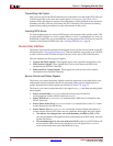
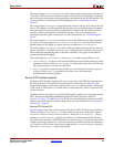
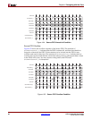
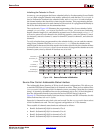
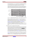
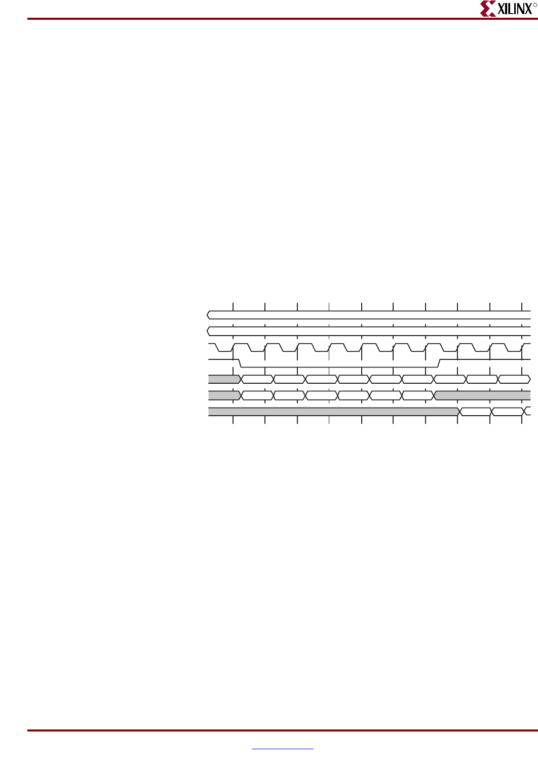
The waveform in Figure 4-28 illustrates the programming of the Source calendar. In this
example, SrcCalendar_Len is set to five and SrcCalendar_M is set to zero (indicating
that the calendar length is six, and should be repeated once). In this example, TStat[1:0]
will receive status for each channel in the following sequence: status for channel 3, status
for channel 0, status for channel 1, status for channel 2, status for channel 3, and status for
channel 0.
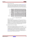
To verify what has been programmed into the calendar buffer, you can read the contents
using Source Calendar Data Out (SrcCalDataOut[7:0]). When the calendar write
enable signal is deasserted, the data stored in the location specified by the calendar address
is driven on the SrcCalDataOut bus. It is not necessary to program the calendar on a one-
channel system, since by default all locations are set to zero.
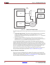
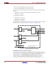
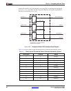
Source Flow Control: Addressable Status Interface
The Addressable Status Interface is 32 bits for all channel configurations. This allows you
to read the FIFO Status Channel data for 16 channels at a time. There are four address lines
(SrcStatAddr) for selecting which 16 channels you are accessing. (Note that for systems
using 1-16 channels, the address lines can be permanently set to zero.) A block diagram of
how the Addressable Interface processes the received SPI-4.2 Status is shown in
Figure 4-29. The minimum latency between the user interface and SPI-4.2 Interface for this
Status Path interface is 9 TSClk cycles.
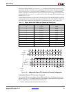
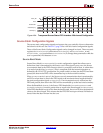
Status for 16 channels in each clock cycle can be read. Use the SrcStatAddr bus to select
which 16 channels are read. The core supports configurations of 1–256 channels.
The accessible 16-channel status banks are addressed as follows:
• Bank 0: SrcStatAddr[3:0]=0 for channels 15 to 0
• Bank 1: SrcStatAddr[3:0]=1 for channels 31 to 16
• Bank 2: SrcStatAddr[3:0]=2 for channels 47 to 32
• Bank 3: SrcStatAddr[3:0]=3 for channels 63 to 48
Figure 4-28: Source Calendar Initialization
SrcCalendar_M
SrcCalendar_Len
SrcCalClk
SrcCalWrEn_n
SrcCalAddr[8:0]
SrcCalData[7:0]
0x00 0x01 0x02 0x03
CH3 CH0 CH1 CH2
SrcCalDataOut[7:0]
0x04 0x05
CH3 CH0
CH3 CH0
0x00 0x01 0x02
SrcCalendar_M=0 (0000.0000)
SrcCalendar_Len=5 (0.0000.0101)