


SPI-4.2 Lite v4.3 User Guide www.xilinx.com 63
UG181 June 27, 2008
Sink Core
R
SnkCalAddr=1, and so forth, until the end of the Calendar is reached, as defined by
SnkCalendar_Len.
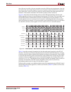
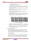
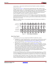
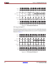
The waveform in Figure 4-7 illustrates the programming of the Sink Calendar. In this
example, SnkCalendar_Len is set to five and SnkCalendar_M is set to zero; indicating
that the calendar length is six, and should be repeated once. This means that the Sink
Calendar will be expected to drive the FIFO Status Channel data (onto the SPI-4.2 bus) in
the following sequence: status for channel 3, status for channel 0, status for channel 1,
status for channel 2, status for channel 3, and status for channel 0.
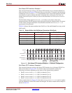
To verify what is programmed into the calendar buffer, read the contents using the Sink
Calendar Data Out bus SnkCalDataOut[7:0]. When the calendar write enable signal is
deasserted, the data stored in the location specified by the calendar address is driven onto
the SnkCalDataOut bus.
Note:
For a 1-channel system, it is not necessary to program the Calendar since, by default, all
locations are set to zero.
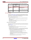
Sink Flow Control
Typically, there are two ways to implement the SPI-4.2 Lite Sink flow control:
• Automatic: For a single channel system or a system that does not require flow control
on a per-channel basis, the SPI4.2 Lite Sink core can be configured to perform flow
control automatically. See “FifoAFMode and Sink Almost Full,” page 67.
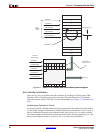
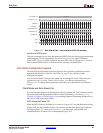
• Manual: When per-channel flow control is required, the interface is fully
customizable. A typical implementation is shown in Figure 4-8. In this case, external
FIFOs are used to provide additional per-channel storage and to facilitate per-channel
flow control. A programmable full indication on the individual user FIFOs can be
used to drive the status interface of the Sink core. This provides flexibility in
implementing the optimal flow control to meet individual system requirements.
If implementing large channel solutions, the individual user FIFOs may be shared by
sets of channels or alternative approaches may be implemented that enable
minimizing the external logic required.
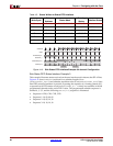
The Sink Status FIFO interface has a 32-bit bus for all channel configurations (e.g., whether
the core is configured for four channels or 128 channels or 256 channels). This allows you
to write the FIFO Status Channel data for 16 channels at a time. There are four address lines
for selecting which 16 channels to access. (For systems using 1-16 channels, the address
lines can be permanently set to zero.) The latency between the user interface and SPI-4.2
Interface for the Sink Status Path is seven RSClk cycles and one SnkStatClk cycle.
Figure 4-7: Sink Calendar Initialization
SnkCalendar_M
SnkCalendar_Len
SnkCalClk
SnkCalWrEn_n
SnkCalAddr[8:0]
SnkCalData[7:0]
SnkCalDataOut[7:0]
0x00 0x01 0x02 0x03
CH3 CH0 CH1 CH2
0x04 0x05
CH3 CH0
CH3
0x00 0x01
SnkCalendar_M=0 (0000.0000)
SnkCalendar_Len=5 (0.0000.0101)