


SPI-4.2 Lite v4.3 User Guide www.xilinx.com 77
UG181 June 27, 2008
Source Core
R
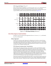
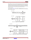
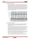
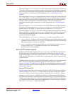
Source Data Path: Example 1
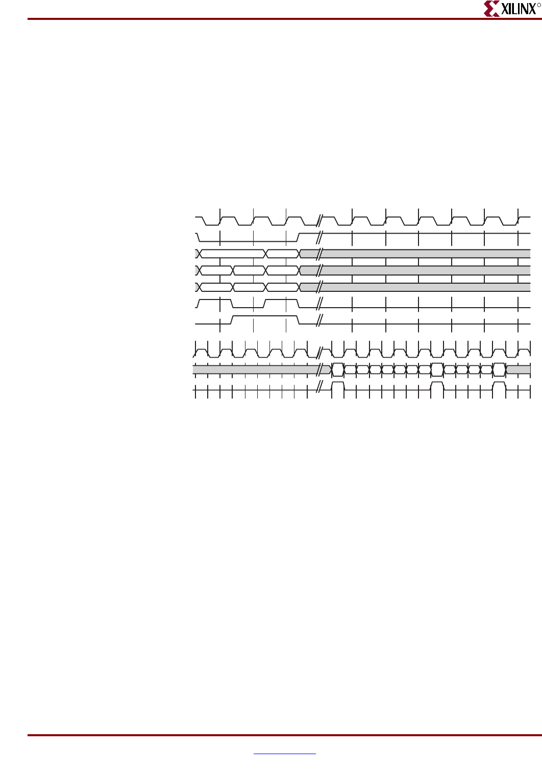
An example of the data received on the user interface and subsequently transmitted on the
SPI-4.2 Interface is shown in Figure 4-21. In this illustration, a 14-byte packet of data is
written into channel 1, followed by an 8-byte packet into channel 2. On the SPI-4.2 bus, the
transfer begins with a payload control word (C1) indicating the start of packet (SOP), and
address of the data to follow. Next, seven SPI-4.2 bus cycles of data, two bytes each, are
used to transfer the data associated with channel 1. The transfer on channel 1 is concluded
with an end-of-packet control word (C2). Because the next FIFO location contains the start
of a new packet on channel 2, the SOP and address of that packet are combined with the
end-of-packet information from channel 1 to form one control word (C2). The second
packet is terminated with an EOP (C3).
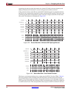
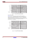
Source Data Path: Example 2
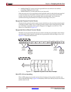
Figure 4-22 shows the transfer of short packets from the Source FIFO to the SPI-4.2 bus
interface. Because each of the packets contain fewer than 14 bytes (or seven SPI-4.2 bus
cycles of data), idle word insertion is necessary to meet the start-of-packet spacing
requirement of eight cycles.
The transfer begins with a 4-byte packet of data for channel 1 written into the Source FIFO.
Next, a 6-byte packet of data is written into the FIFO for channel 2. Finally, a 4-byte packet
for channel 3 is written into the FIFO. The transfer on the SPI-4.2 bus begins with a control
word (C1) indicating a start-of-packet for channel 1. Next, the four bytes of data for
channel 1 are transferred. While the FIFO contains the start-of-packet information for
channel 2, that information cannot be combined with the end-of-packet information from
channel 1 because of the 8-cycle start-of-packet spacing requirement.
For this reason, five additional idle control words (I) are sent across the SPI-4.2 bus with the
first idle control word containing the end-of-packet information for channel 1. The next
SPI-4.2 cycle contains the start-of-packet and address information for channel 2 (C2). This
payload control word is followed by the six bytes of data for channel 2.
Again, because of the start-of-packet spacing requirement, another four cycles of idle
control words (I) must be sent across the interface with the first idle control word
Figure 4-21: Source Data Path: User Interface to SPI-4.2 Interface
CH1
1E 1F 10 --1A 1B 1C 1D
CH2
2A 2B 2C 2D
110000 000
SrcFFClk
SrcFFWrEn_n
SrcFFAddr
SrcFFData
SrcFFMod
SrcFFSOP
SrcFFEOP
TDat_P
TDClk_P
TCtl_P
C1 1A 1B 1C 1D 1E 1F C2 2A 2B 2C 2D10 C3