


SPI-4.2 Lite v4.3 User Guide www.xilinx.com 85
UG181 June 27, 2008
Source Core
R
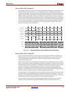
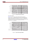
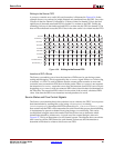
Writing to the Source FIFO
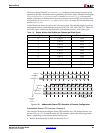
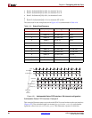
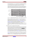
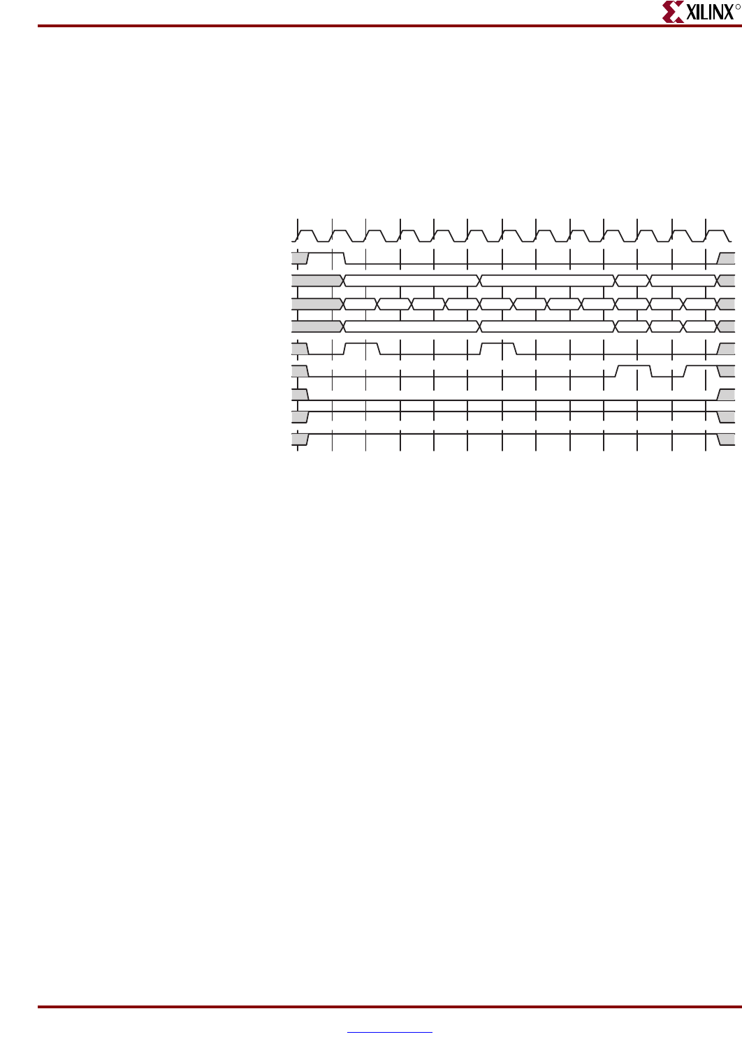
A pause to a transfer on a credit (16 bytes) boundary is illustrated in Figure 4-26. In the
example shown, two packets for unique channels are transferred into the FIFO. You write
32 bytes of data for channel 1, followed by 32 bytes of data for channel 2. Next, the final
eight bytes of data and associated EOP for channel 1 is written to the FIFO. Finally, the
remaining 16 bytes of data and associated EOP is written into the FIFO for channel 2. The
data will be transferred across the SPI-4.2 bus in the same order it is written into the FIFO
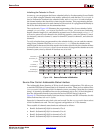
Insertion of DIP-4 Errors
The Source core enables you to force the insertion of DIP4 error for use during system
testing and debugging. This is supported by the SrcFFErr signal. When a SrcFFEOP flag
is asserted, SrcFFErr is used to indicate that the current packet contains an error and
causes the core to transmit an EOP abort with the packet. When SrcFFEOP is not asserted,
the assertion of SrcFFErr causes the core to force the insertion of an EOP (1 byte or 2 bytes
depending on SrcFFMod) with an erroneous DIP4 value when this data is transmitted on
the TDat bus. The erroneous DIP4 value is an inversion of the correctly calculated DIP4
value. Note that the DIP-4 error insertions are independent of
SrcFFSOP.
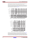
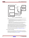
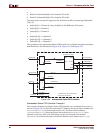
Source Status and Flow Control Signals
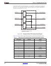
The Source core transmits data in the order that it was written to the FIFO. You can pause
data transmission by sending idle cycles (using IdleRequest) or training
(TrainingRequest), but unless the FIFO is cleared (Reset_n or SrcFifoReset_n), the
data written into the FIFO will be transmitted in order. Ensure that proper data scheduling
is implemented to prevent a channel from going hungry or overflowing. This can be
accomplished using the status information from the Source core to determine which
channel data should be written next. A typical user flow-control design is shown in
Figure 4-27. This is an illustration of a two-channel system. The diagram shows an arbiter
that is used to poll the FIFO Status for each channel. It then uses this information to
determine which data is written to the Source core FIFO.
Figure 4-26: Writing to the Source FIFO
SrcFFClk
SrcFFWrEn_n
SrcFFAddr
SrcFFData
SrcFFMod
SrcFFSOP
SrcFFEOP
SrcFFErr
SrcFFOverflow_n
SrcFFAlmostFull_n
CH1
000 000
CH2 CH1 CH2
000