


SPI-4.2 Lite v4.3 User Guide www.xilinx.com 29
UG181 June 27, 2008
Sink Core Interfaces
R
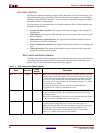
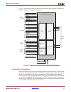
Sink Clocking Interface
The Sink core supports two clocking implementations: embedded clocking and user
clocking. The embedded clocking configuration provides a complete solution with the
clock circuitry embedded within the Sink core. The user clocking configuration allows the
clocking scheme to be implemented external to the Sink core.
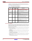
A list of the Sink clocks for embedded clocking and their description is provided in
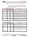
Table 2-7. Table 2-8 defines the DCM reset and clock status signals, and Table 2-9 defines
the user clocking signals. The minimum frequency for all clocks is dependent on the
minimum frequency of the DCM.
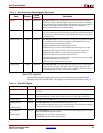
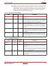
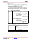
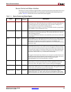
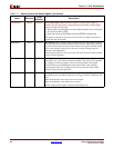
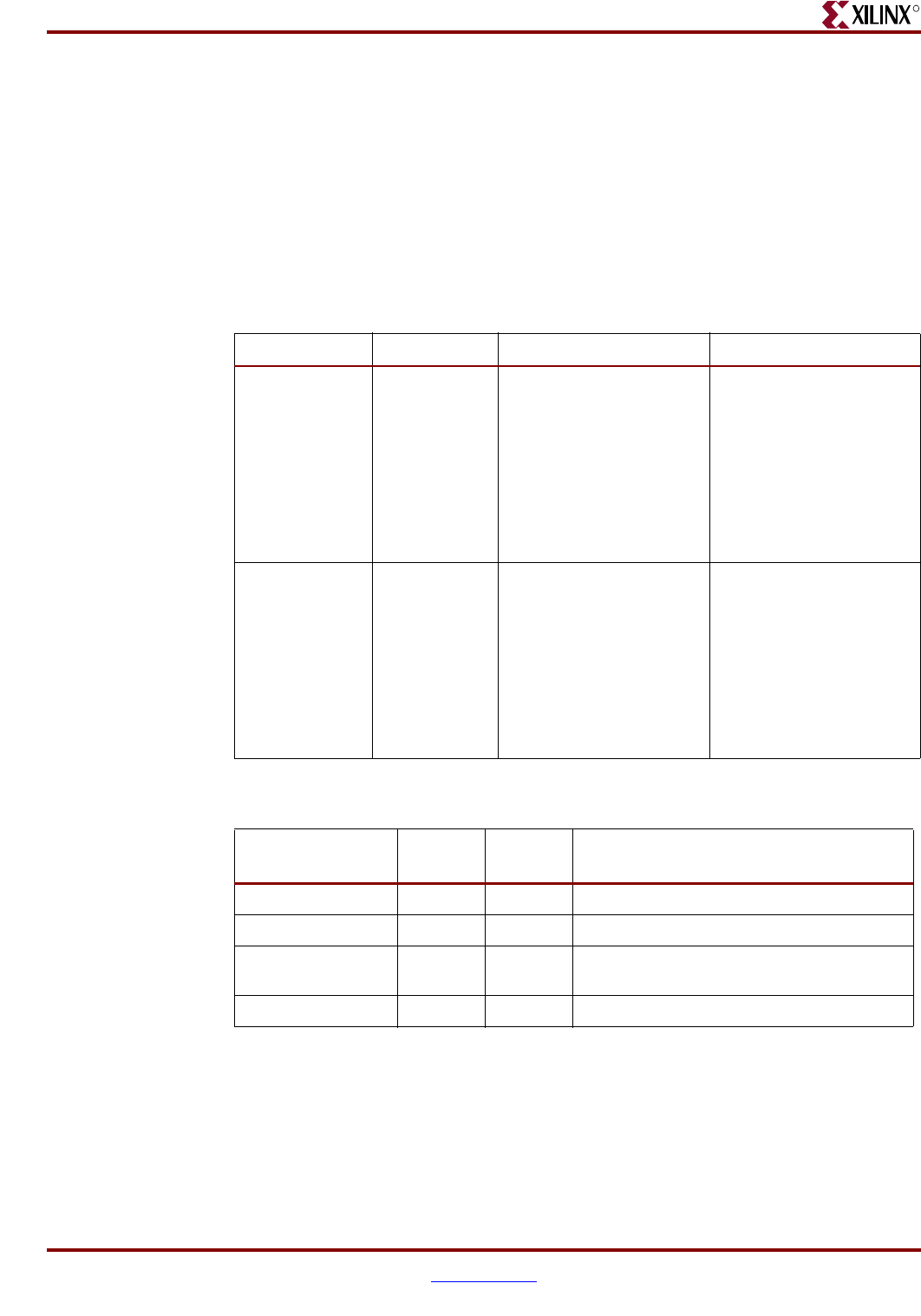
Table 2-7: Sink Core Clocks: Embedded Clocking
Clock Pins Direction Description Max. Frequency
RDClk0_GP Output
(User Interface)
RDClk0 General Purpose:
This clock is the full Rate
Receive Data Clock. It is
used for clocking the
internal logic of the core and
is routed to the User
Interface for use by the
user’s logic.
Virtex-5: 275 MHz
Virtex-4: 190 MHz
Virtex-II Pro: 160 MHz
Virtex-II: 160 MHz
Spartan-3: 115 MHz
Spartan-3E: 90 MHz
Spartan-3A/3AN/3A DSP:
105 MHz
RDClk180_GP Output
(User Interface)
RDClk180 General
Purpose: This clock is the
inverted equivalent of
RDClk0_GP. It is used for
clocking the internal logic of
the core and is routed to the
User Interface for use by the
user’s logic.
Virtex-5: 275 MHz
Virtex-4: 190 MHz
Virtex-II Pro: 160 MHz
Virtex-II: 160 MHz
Spartan-3: 115 MHz
Spartan-3E: 90 MHz
Spartan-3A/3AN/3A DSP:
105 MHz
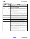
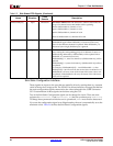
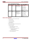
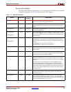
Table 2-8: Sink Core Clocks: Status Signals
Name Direction
Clock
Domain
Description
DCMReset_RDClk Input N/A Reset of RDClk’s DCM
Locked_RDClk Output N/A Locked status of RDClk’s DCM
DCMLost_RDClk Output N/A Indicates RDClk input has stopped (status bit
one of RDClk DCM)
SnkClksRdy Output N/A Indicates all Sink core clocks are ready for use