


SPI-4.2 Lite v4.3 User Guide www.xilinx.com 53
UG181 June 27, 2008
Sink Core
R
• Initializing Status Calendar
After the core exits the reset mode, the sink and status calendars must be initialized or
programmed. There are two ways to do this:
♦ Initialize calendar with a default value: Using the CORE Generator GUI load an
initialization file with the calendar contents. See Chapter 3, “Generating the Core”
for more information.
♦ Programming calendar after reset: Using the calendar control interface to
program the calendar contents. See “Sink Calendar Initialization,” page 62 and
“Source Calendar Initialization,” page 86 sections for more information.
After initializing the core, it can be enabled for operation.
Sink Core
Basic Operation
The Sink core receives data across the SPI-4.2 Lite interface and converts the 16-bit data
into 32-bit or 64-bit data words that can be accessed on the user interface. It also transmits
flow control information on the SPI-4.2 Lite interface by converting a 32-bit status bus to a
2-bit status word.
The following sections explain how the sink core interfaces operate. See “Sink Core
Interfaces,” page 19 for the signal list of each interface.
SPI-4.2 Interface
The SPI-4.2 data path combines 16-bit data words received on the SPI-4.2 Interface into 32-
or 64-bit data words. This allows you interface to run at half (32-bit interface), or a quarter
(64-bit interface) of the data rate. For example, for a 200 Mbps SPI-4.2 data rate and a 32-bit
user interface, you can read data from the Sink core at 100 MHz. If a 64-bit user interface is
used, data can be read from the Sink core at 50 MHz and maintain the same data rate.
After the data path combines the 16-bit data words received on the SPI-4.2 interface, the
data words are written into an asynchronous FIFO. The received 16-bit control words are
stored out of band in the FIFO, along with the corresponding data word. The received
control words that are not idle (training words) can contain the information listed below:
• Start or continuation of the following packet
• Link address of the following packet
• End of the preceding packet
• Number of valid bytes in the last word of the preceding packet
• Error conditions in the preceding packet
For details about the assignment of each bit in the control word, as defined by the OIF SPI-
4.2 specification, see Appendix A, “SPI-4.2 Lite Control Word.”
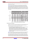
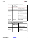
Sink Data Path: Example 1
Figure 4-1 is an example of data received on the SPI-4.2 Interface and read on the 64-bit
user interface. In this example, the first received control word (C1) is a payload resume
(with no SOP) for channel 1, followed by two 16-bit words (channel 1, packet A and packet
B). The second control word (C2) is an EOP for channel 1 and a payload resume for channel
2 (with no SOP), followed by two 16-bit words. The third control word (C3) is an EOP for